

Optimization of Heat Sink for CPU Cooling
Abstract
Abstract
Google Meet Link: meet.google.com/mgj-kjci-oss
Aim:-
To optimize the design of a heat sink using computational tools and simulations to enhance heat dissipation efficiency for CPU cooling under forced convection.
Theoretical Learning:-
The operation of a heat sink involves three main steps: conduction, spreading, and convection. First, heat is conducted from the hot surface of the component into the body of the heat sink. Once inside the heat sink, the heat spreads across its extended surface area—typically composed of fins or other features designed to maximize exposure to air. Finally, the heat is transferred from the surface of the heat sink into the air (or another cooling medium) primarily through convection, and to a lesser extent through radiation.
Since it is a convective transfer, equations can be modelled in two ways,
- Heat Coefficient Method
- Fluid Flow (Natural/Forced Convections)
Different approaches carried out and results will be presented.
Procedure:-
The project was carried out in four segments:
- Modelling of Traditional Plate Heat Sink(0deg)
- CFD Simulation of TPHS (Forced Convection)
- CAD Modelling of Heat Sink with Sloped Geometries
- CFD Simulation of Heat Sink with Sloped Geometries
1. Modelling of Traditional Plate Heat Sink:-
- Geometry parameters of the heat sink were directly taken from available research.(3)
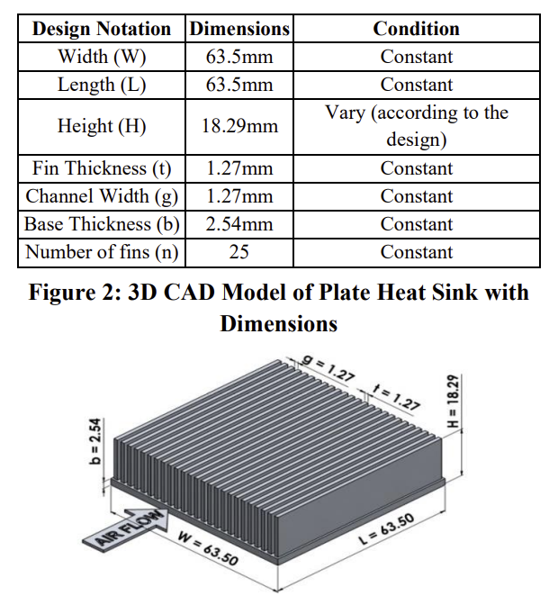
- Model of the heat sink was prepared in Autodesk Fusion 360. Simple tools like extrude and rectangular pattern were used.
- The sketch of the fin shape was designed in such a way that parameters could be changed.
2. CFD Simulation of TPHS:-
- To perform a CFD simulation, the necessary steps were followed as shown in the figure below.

Once the geometry was imported into Ansys Fluent,
- An outer air region was defined to simulate airflow and unstructured mesh was generated(element size: 5mm /5e-3m). Finer mesh applied separately to the heat sink and CPU chip(element size: 1.5mm /1.5e-3m). Total 632912 elements were generated with 112797 nodes.
- Named selections were created for the inlet, outlet, heat sink walls, and chip region.
- In Solver Phase, Energy Equation was enabled to model heat transfer and laminar flow was assumed due to low-speed (1 m/s) air conditions.(3)
- Copper was selected for heat sink and chip and air with standard properties.
- Power density was applied to the chip to simulate CPU heat generation (in W/m³).
After the simulation, results were visualized using contour plots, as shown below.
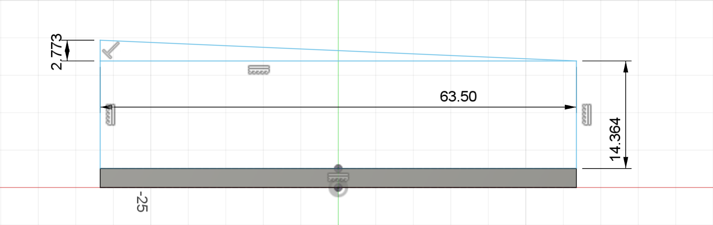
3. CAD Modelling of Heat Sink with Sloped Geometries:-
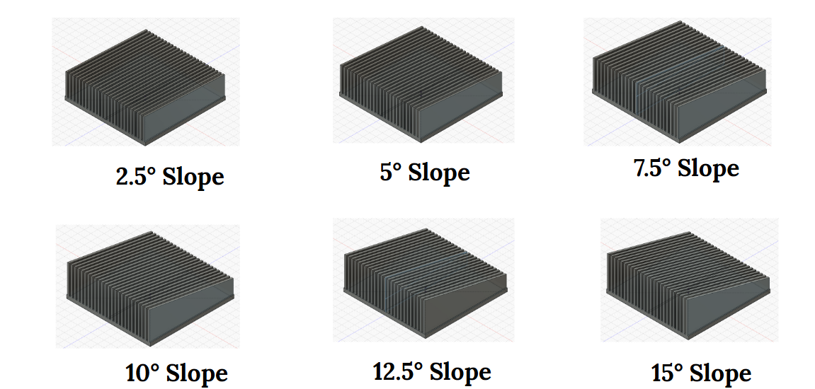
To assess how fin slope affects heat dissipation, the plate heat sink design was modified by varying the slope of the fins.
- Fins were redesigned to incorporate triangular cross-sections, producing slopes ranging from 2.5° to 15° in 2.5° increments.
- Careful adjustments were made to maintain the same overall size of the heat sink.
- For each model, the slope angle and corresponding triangular fin heights were calculated to maintain consistent heat sink size and mass distribution.(3)
| Slope Angle | Rectangular Height | Triangular Height |
| 0 | 15.75 | 0 |
| 2.5 | 14.3638 | 2.7725 |
| 5 | 12.9722 | 5.5555 |
| 7.5 | 11.5701 | 8.3599 |
| 10 | 10.1516 | 11.1968 |
| 12.5 | 8.7112 | 14.0776 |
| 15 | 7.2426 | 17.0148 |
(Angles are in degrees and heights in mm)
- Different sinks were created with the above parameters in Fusion360 as shown below.
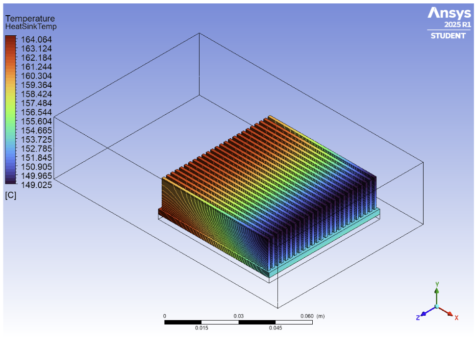
4. CFD Simulation of Heat Sink with Sloped Geometries:-
Each sloped heat sink geometry was subjected to the same CFD simulation environment as the traditional (0°) model to maintain consistency and allow for fair comparison.
- Temperature contours were generated for each design.
- The maximum temperature on the heat sink surface and the average temperature on the chip were recorded.
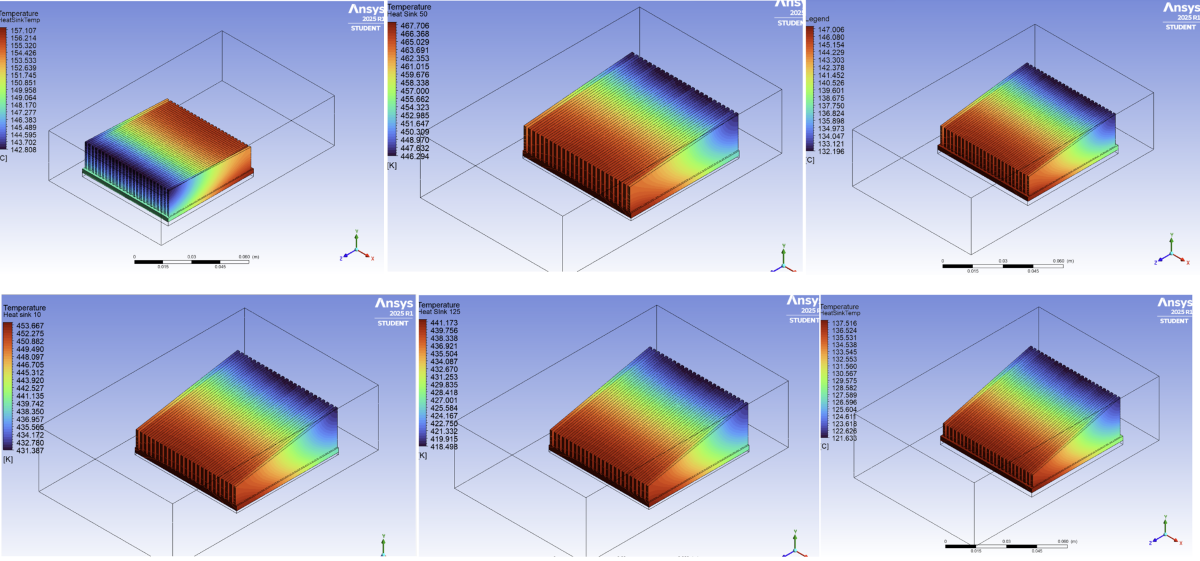
(Two set of results were created by mentees individually. Above image contains some of them)
Different Approach:-
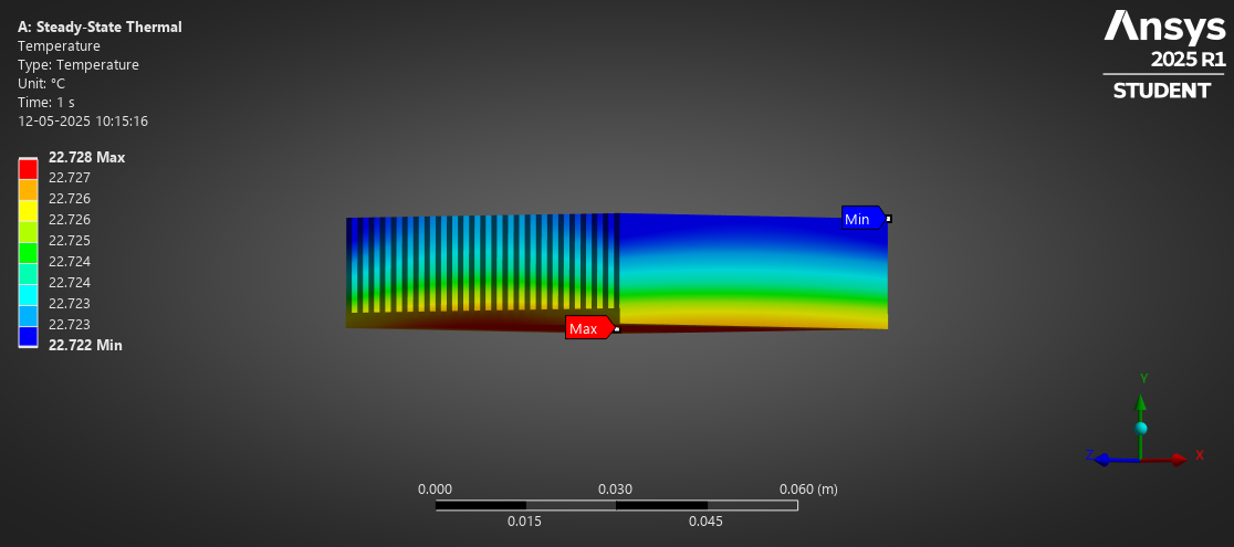
In addition to CFD simulations, a simplified steady-state thermal simulation was conducted using:
- Linearly varying film coefficients for convective boundaries.
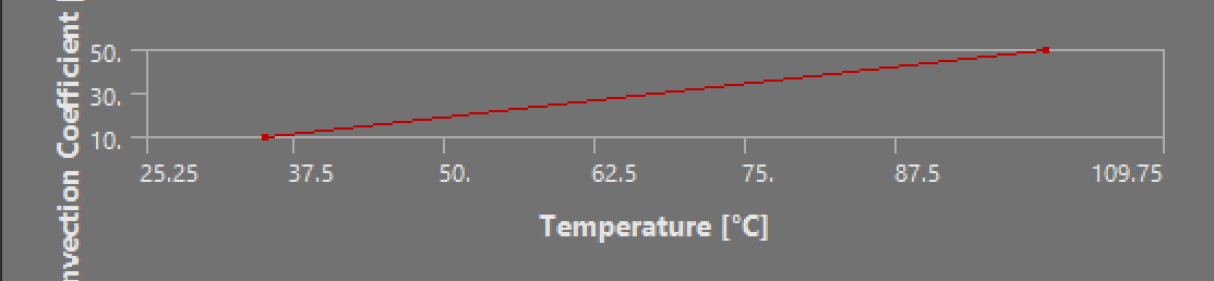
- Basic heat transfer equations without modelling the airflow directly.
- This approach provided quick estimates and validated trends observed in detailed CFD.
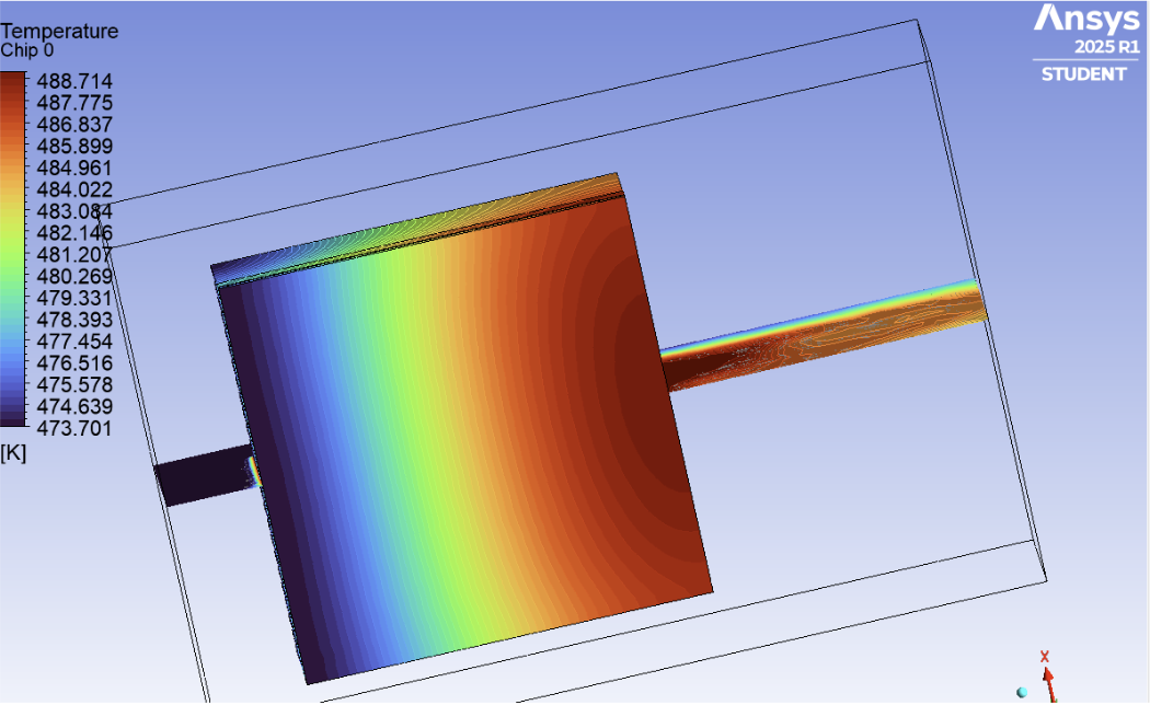
Results & Conclusion:-
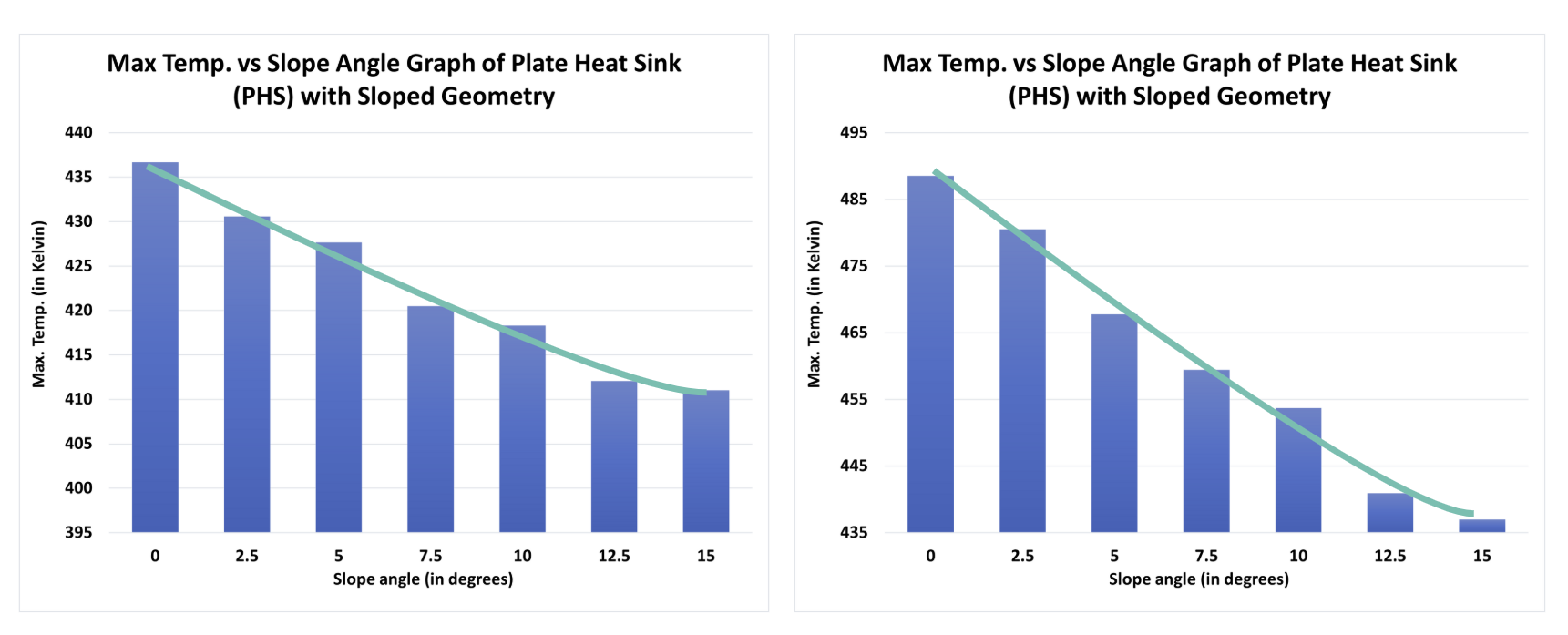
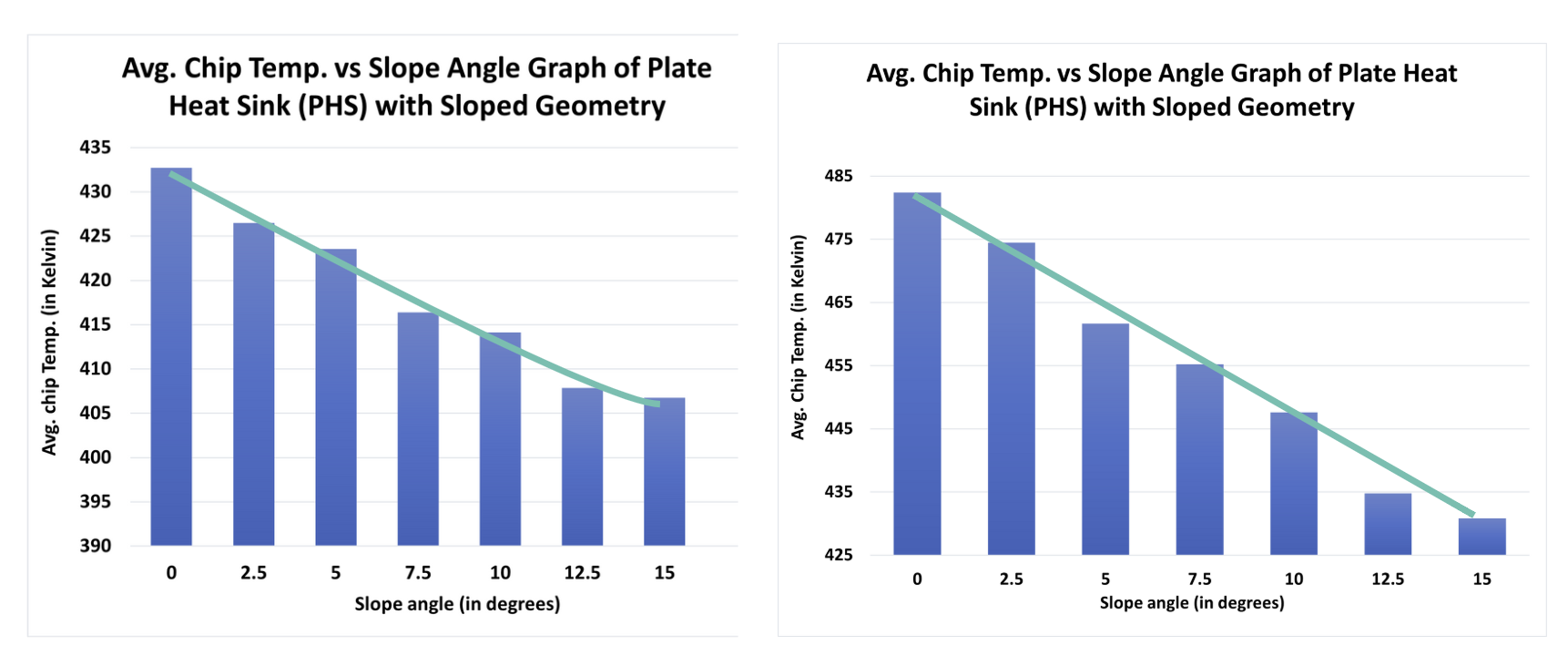
(Above images show results obtained by different mentees)
- In given case, sloped heat sink proves to be more efficient in dissipating heat.
- As both the maximum temperature of the heat sink and the average temperature of the chip decrease, only constraints remain are geometric i.e. maximum possible slope for given heat sink parameters.
- The steady-state thermal analysis is helpful for estimating parameters for basic geometry quickly.
Future Possibilities:-
- Our study assumed forced convection of 1m/s directed air. In such case, a varying (non-uniform) cooling pattern can be seen in the chip for all cases.
- To counteract this, a detailed study on vertically down forced convections with four outlets and varied fin shapes can be done to achieve better results.
Mentees:-
Vishnu D
Dnyaneshwari Deore
Mentors:-
Arpit Hatila
Nandeesh Trivedi
Lianna Mascarhenas
Hridya Vinu
Dhanya
References:-
(1)GitHub Repository
(2)Reference Thesis by EMRE ÖZTÜRK
(3)Study of Active Plate Heat Sink using Different Slope Angles
(4)A hands on introduction to engineering simulations
(5)ANSYS Fluent: Electronics Cooling Forced Convection | Tutorial
Report Information
Team Members
Team Members
Report Details
Created: May 21, 2025, 12:57 p.m.
Approved by: Prudhvi Nallagatla [Piston]
Approval date: May 24, 2025, 12:07 p.m.
Report Details
Created: May 21, 2025, 12:57 p.m.
Approved by: Prudhvi Nallagatla [Piston]
Approval date: May 24, 2025, 12:07 p.m.