

Arduino Multimeter
Envision
Diode
Abstract
This project presents the development of a low-cost, Arduino-based digital multimeter capable of measuring five fundamental electrical quantities: voltage, resistance, capacitance, inductance and diode's forward voltage. The system reads electrical signals using simple circuit techniques such as voltage dividers and shunt resistors, and displays the measured values on a 16x2 LCD screen. Designed primarily for educational and prototyping purposes, this multimeter offers a compact and affordable solution for basic electrical measurements.
A Project By:
Mentors: Kanishk Choudhary, Mohnish Raj Mani, Sathvika Bandi
Mentees: Arya Arikeri, Vineet Kumar Singh, Vaibhav Porwal
Google Meet Link:- https://meet.google.com/kkj-kvuj-uxr
GitHub Repository:- https://github.com/SathvikaBandi14/5-in-1-Arduino-Multimeter
Aim
The aim of the project is to successfully design a multimeter using Arduino that can measure and display basic electrical parameters such as voltage, resistance, and capacitance.
Introduction
A multimeter is an essential tool used to measure basic electrical parameters such as voltage, current, and resistance. This project focuses on designing a simple and cost-effective digital multimeter using an Arduino board. By employing basic circuit techniques like voltage dividers and sensing resistors, the device can accurately measure electrical quantities and serve as a practical learning tool for students and electronics enthusiasts.
Literature Survey
Digital multimeters are vital instruments used to measure electrical parameters such as voltage, current, and resistance. The evolution of multimeters has transitioned from purely analog devices to sophisticated digital instruments that offer higher accuracy, multiple functions, and user-friendly interfaces.
1. Early Digital Multimeters
Early digital multimeters used discrete analog components and dedicated ADC chips to convert analog signals into digital readings. These devices often relied on complex circuitry and were relatively expensive. Early attempts to design DIY digital multimeters utilized microcontrollers such as PIC and AVR series. These microcontrollers facilitated digital processing of signals and simplified calibration and display. However, the limited processing power and resources often restricted their functionality.
2. Arduino-Based Multimeters
The introduction of Arduino revolutionized hobbyist electronics, enabling rapid prototyping with an easy-to-use platform. Numerous projects have documented the development of Arduino-based multimeters capable of measuring voltage, current, and resistance by leveraging Arduino’s built-in 10-bit ADC. These designs typically use voltage dividers for voltage measurements and shunt resistors for current sensing, paired with resistor-based circuits to measure resistance.
Many Arduino multimeter projects display readings on 16x2 LCDs or via serial communication to a computer, enhancing usability and data logging. Arduino’s open-source nature and large community support have led to continuous improvements and additional features such as capacitance measurement and auto-ranging.
Methodology
This Multimeter measures various physical parameters by using very basic principles such as ohms law, RC circuits etc.
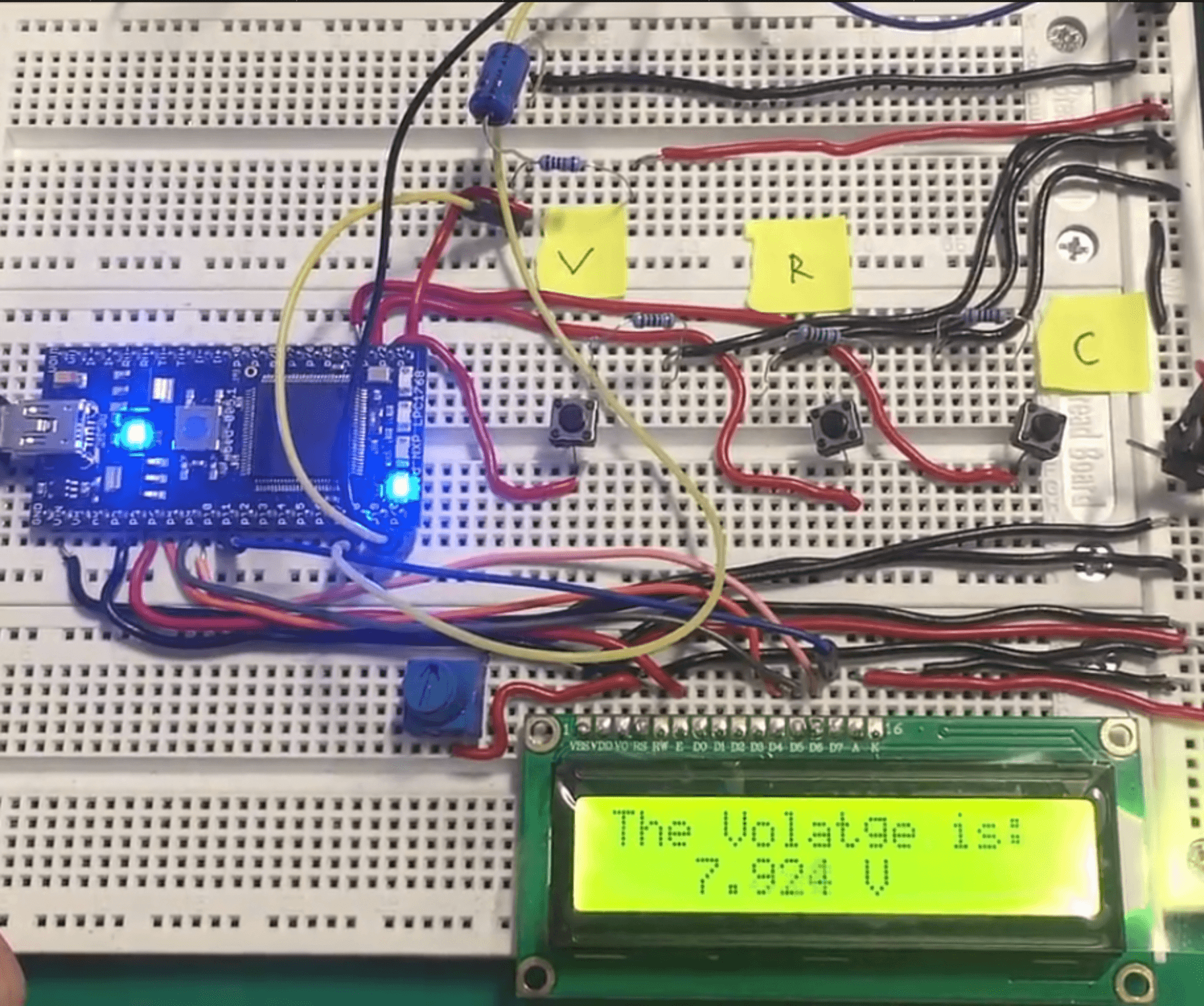
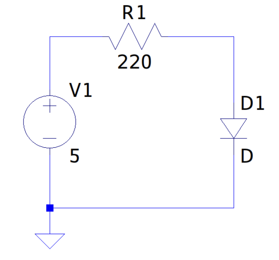
1. Voltage
-
Voltage could be measured by scaling the external higher voltage to 0-5v which is suitable for arduino.The arduino measures the voltage through its digital input pin in the range from 0 to 1023, which can be scaled down to 0 to 5v.
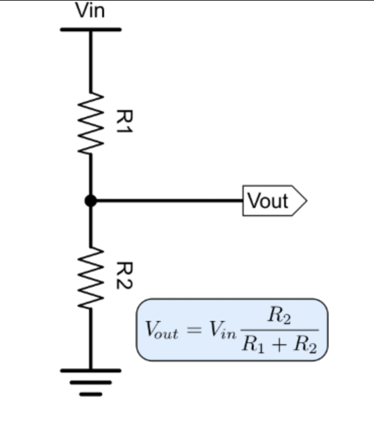
2. Resistance
-
For measuring a resistor, we can connect it to a known comparable resistor and then applying a voltage to it. Then according to voltage divider formula we can estimate the resistor value.
-
We already have a known resistor in the circuit and can calculate V(out) and V(in) with the help of the digital input pins of arduino, then calculate R1 with the help of the voltage divider formula (given in above figure).
3. Capacitance
-
For capacitance we can use a simple RC circuit, apply a known voltage and resistance to it then measure the time taken for the capacitor to charge to 50%. After that we can use the formula given below to calculate capacitance
C = -t / ( R * ln(2) )
where 't' is the charging time and 'R' is the known resistance from the circuit
4. Inductance
-
When an LC tank circuit is given an impulse input, it starts to oscillate at its resonance frequency. This oscillation dies out after a while due to the resistance present in the circuit. We can measure that frequency using the arduino by first converting the sinusoidal oscillation to a square wave oscillation and checking the time duration between those pulses. To do this we can use the internal comparator present in the arduino.
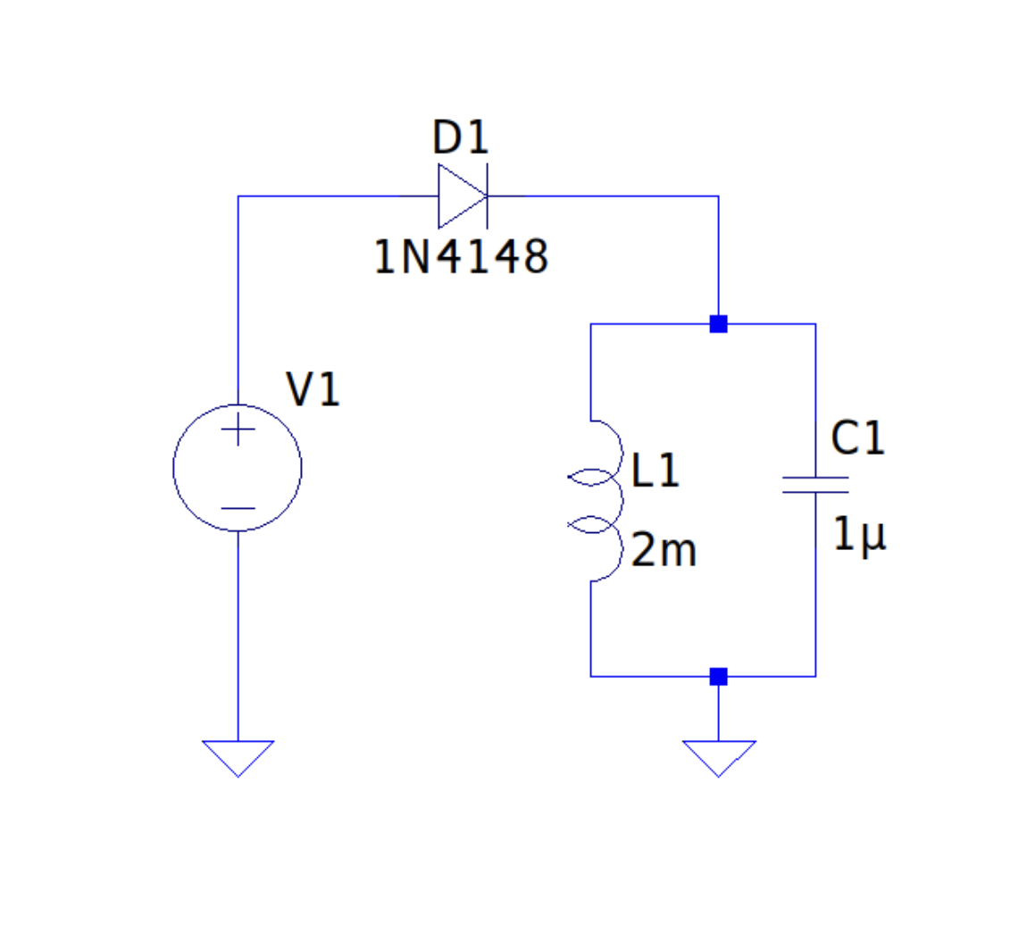
At resonance, the reactances of inductor and capacitor will be equal, therefore
Xl = Xc
w.L = 1/(w.C)
w = 1 / sqrt(LC) ← this is the resonance frequency of the LC tank
So if we find this, we can find the value of inductance as:-
L = 1/(C.w^2)
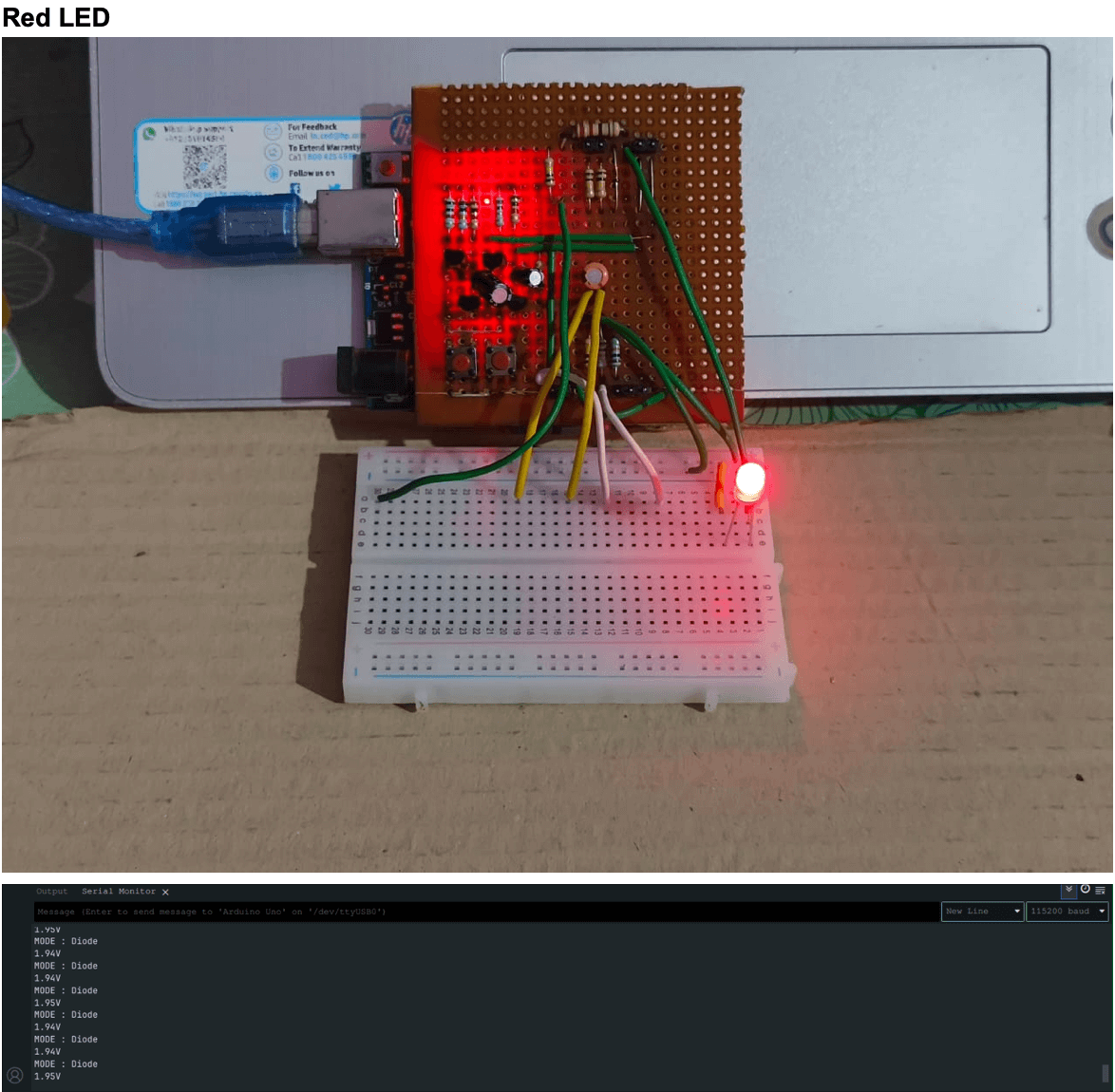
5. Diode's Forward Voltage

-
The voltage drop across a diode depends on the current flowing through it. When the diode is forward biased, the current through the diode is nearly 0 till the applied voltage is near the knee voltage. When the applied voltage is more than the knee voltage of the diode, the current rapidly increases. Then the voltage across the diode could be considered nearly constant for a very large change in current. For example, for silicon diodes, its typically considered 0.6-0.7V.
-
Since this voltage is nearly constant, it becomes a useful property to know about a diode. So by passing a reasonably large current through it and reading the voltage across it, we can determine its knee voltage
Results
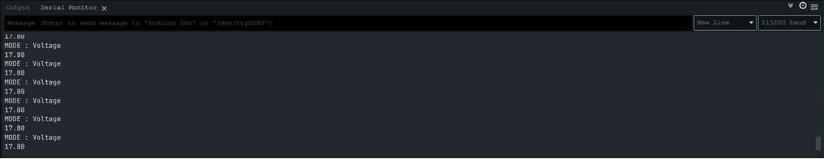
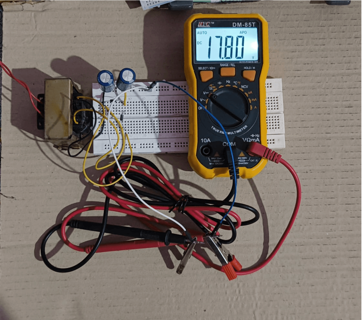
1. Voltage
From arduino multimeter :-
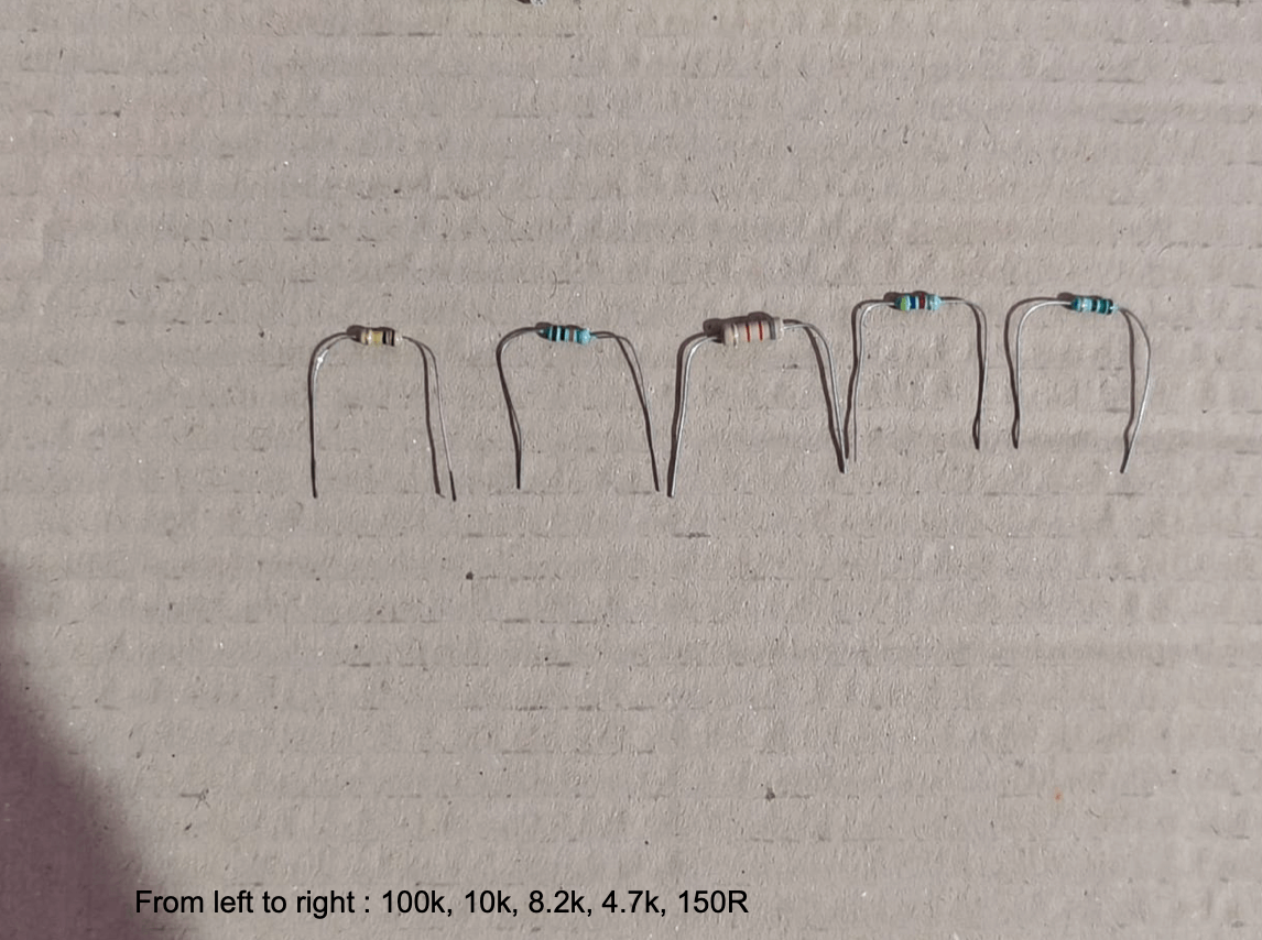
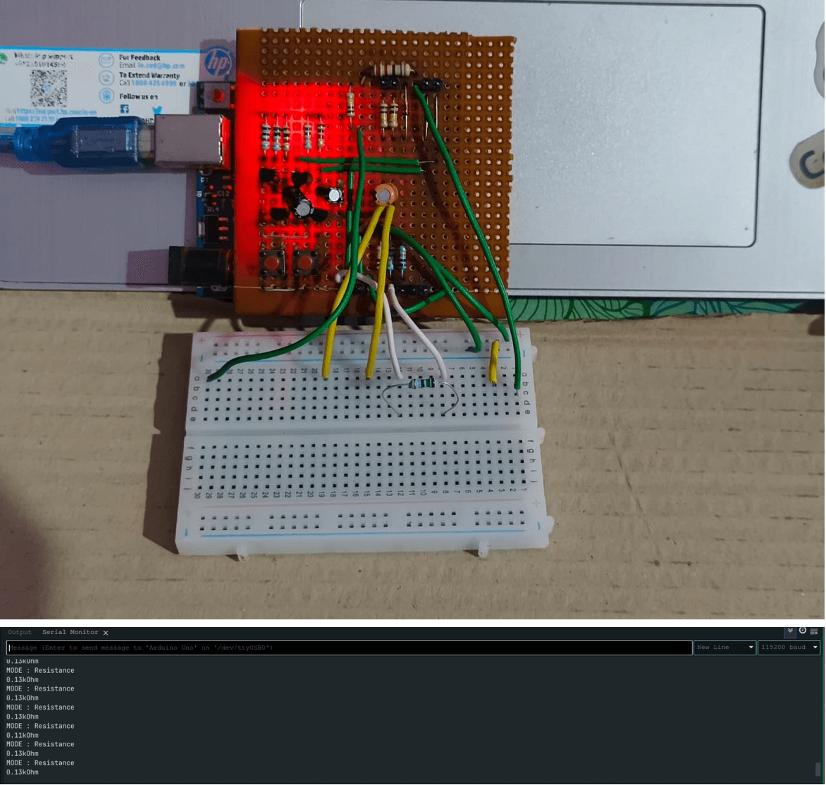
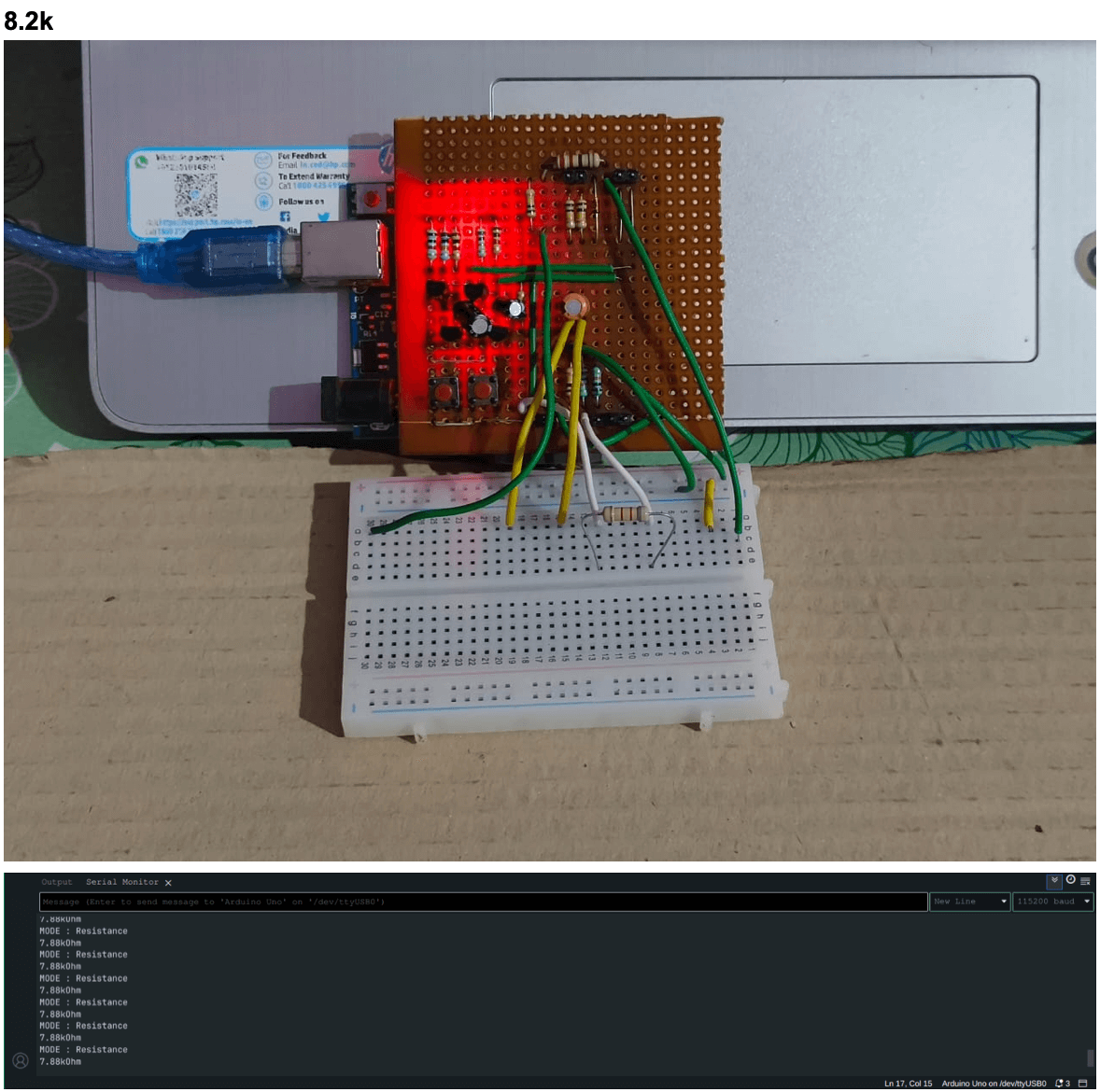
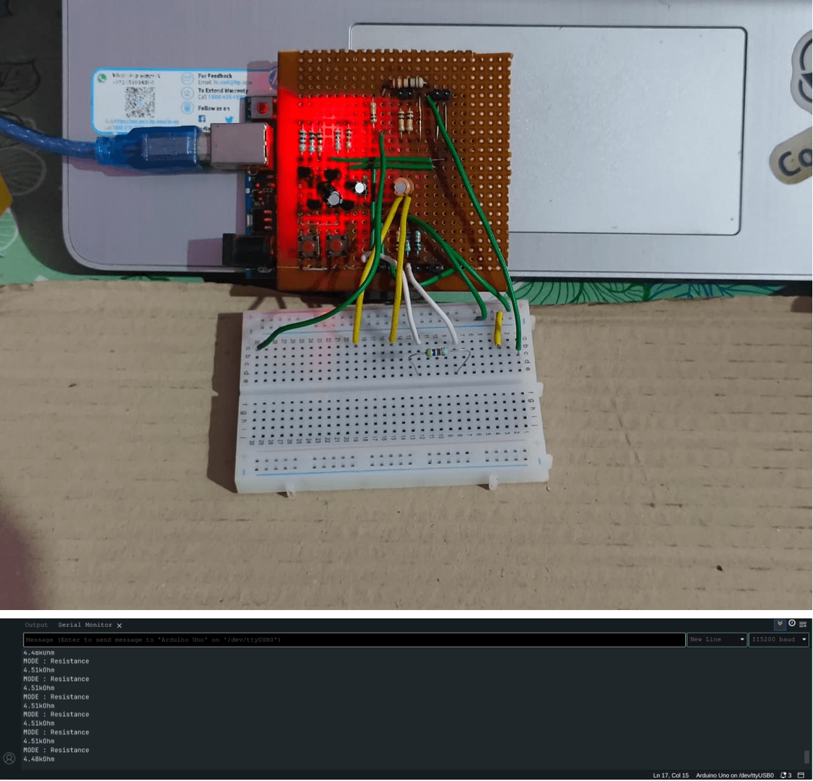
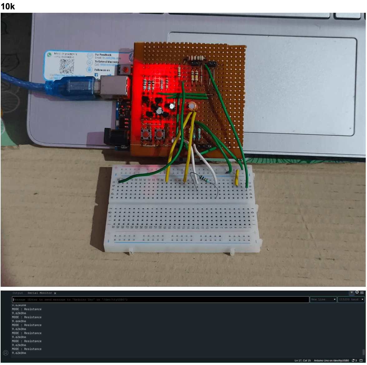
2. Resistance
Test Resistors used and values:-
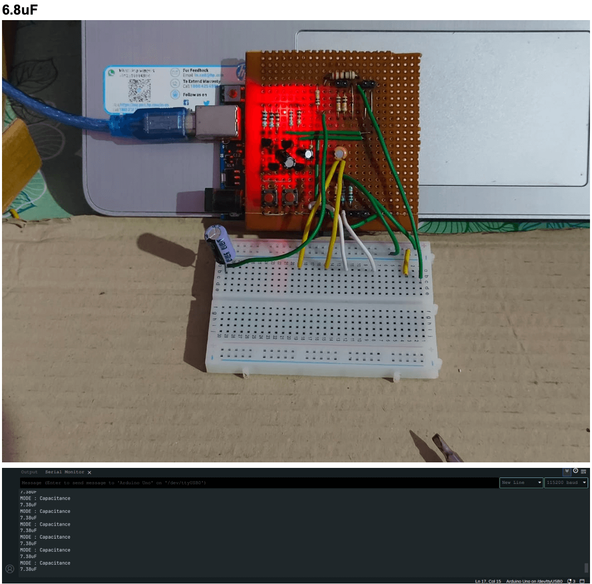
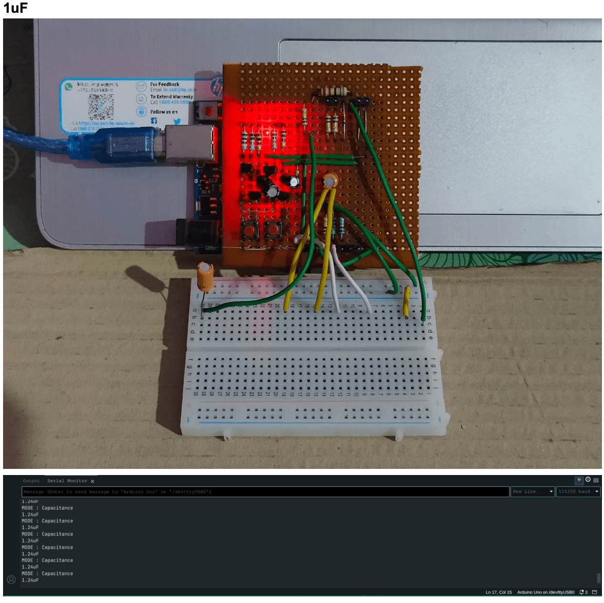
3. Capacitance
4. Inductance


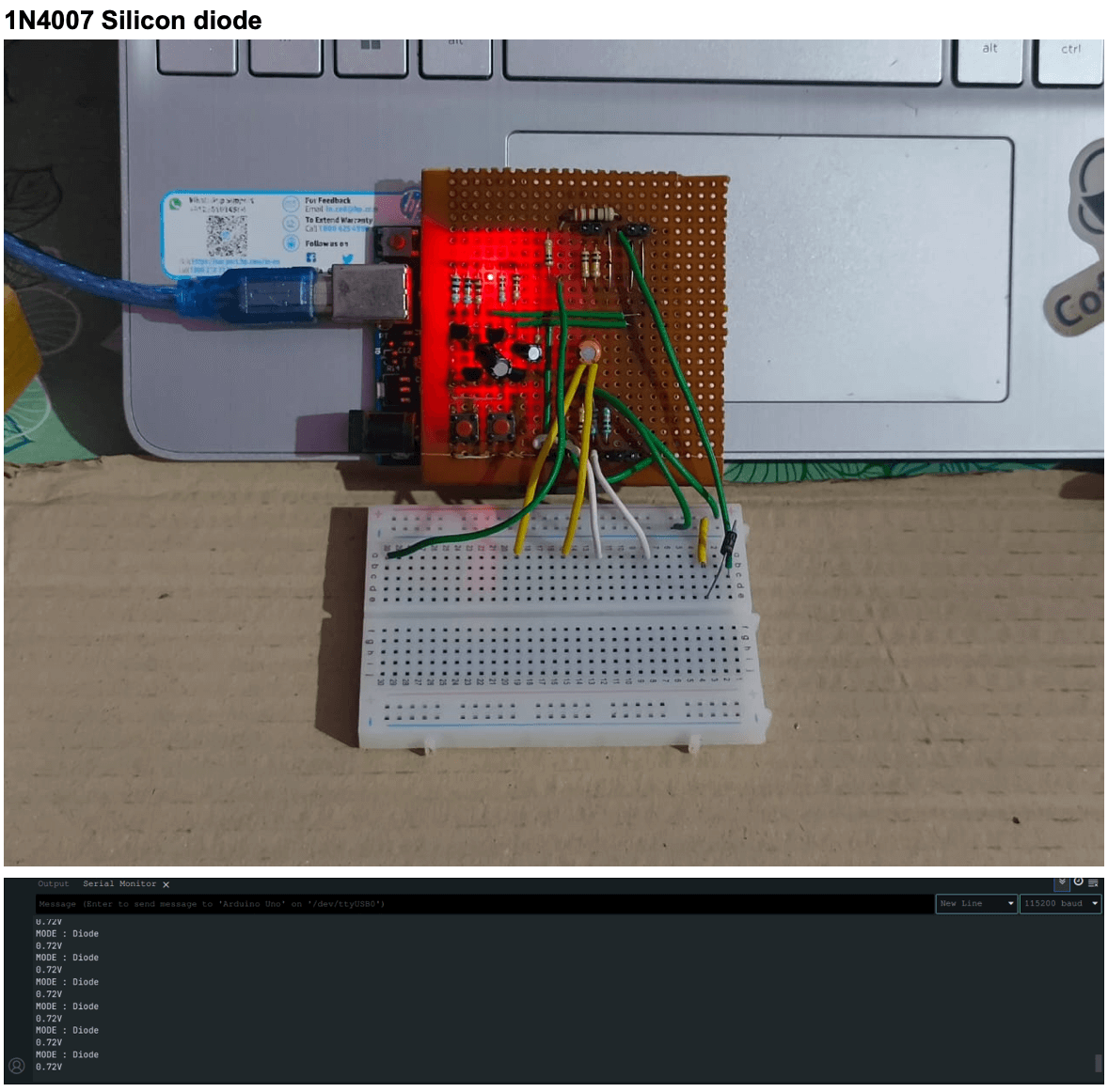
5. Diodes Forward Voltage
Future Scope
There are many ways this Arduino multimeter project can be taken further. Adding features like measuring frequency, temperature, and power factor would make it useful for more types of electrical testing. It would also be great to include an auto-ranging function so the multimeter can automatically pick the right measurement scale, making it easier to use and more accurate.
Another exciting possibility is adding wireless connectivity, like Bluetooth or Wi-Fi, so you could monitor readings or log data right from your phone or computer. These kinds of improvements would make the multimeter more flexible and practical, whether for hobbyists, students, or even more advanced electronics work.
Conclusion
The Arduino-based multimeter successfully measures multiple electrical parameters including voltage, resistance, capacitance, inductance, and the forward voltage of diodes. The project demonstrates how an affordable microcontroller platform can be used to build a versatile and functional measuring instrument. By integrating simple sensing circuits with Arduino’s processing capabilities, the device provides accurate and reliable readings suitable for educational and hobbyist use.
Report Information
Report Details
Created: May 22, 2025, 9:57 p.m.
Approved by: Adithya Kasal [Diode]
Approval date: May 25, 2025, 4:53 p.m.
Report Details
Created: May 22, 2025, 9:57 p.m.
Approved by: Adithya Kasal [Diode]
Approval date: May 25, 2025, 4:53 p.m.