

S.P.F.A.C-32: 32-bit Single Precision Floating Arithmetic Core
Abstract
Abstract
Project Presentation Link:
https://meet.google.com/kwn-mkea-csg
Mentees:
Vikram Singh
Krish Mehta
Parv Mahajan
Yagya Sharma
Ashwal R Shanbhag
Shamit Hoysal
1 Abstract:
This project focuses on the design and simulation of a 32-bit Floating Point Arithmetic Logic Unit (ALU) compliant with the IEEE 754 Single Precision Standard, implemented using Verilog HDL on the Vivado design platform. The ALU supports the three core arithmetic operations—addition, subtraction, and multiplication—on floating-point numbers. The implementation targets accuracy, efficiency, and reduced logical complexity while handling the full range of IEEE 754 representations, including special cases such as zero, infinity, NaN, and overflow.
2 Introduction
2.1 Motivation and Background
Floating-point arithmetic plays a critical role in modern computing, enabling the accurate and efficient handling of real numbers across a wide range of applications. It represents a large range of values ( 10-38 to 1038 in 32-bit IEEE 754). The IEEE 754 has a widespread range of representing numbers with a precision of 7-8 digits after the decimal. The IEEE 754 standard ensures consistency and reliability across CPUs, GPUs, and software platforms. In Signal processing it caters for the precise operation of converting analog to digital signals . Digital filters (FIR/IIR) use floating-point arithmetic to maintain accuracy and prevent overflow/underflow. Precise and fast floating-point operations are essential for smooth, real-time rendering in games and simulations. 3D rendering relies heavily on matrix and vector math using floating-point.The IEEE 754 standard, established in 1985, defines the format and behavior for floating-point computation, ensuring consistency and portability across platforms. Implementing floating-point arithmetic at the hardware level is crucial for performance-intensive applications.
The need for designing a custom FPU is driven by the need to optimize performance , precision and power efficiency . Significant gains in execution speed, area efficiency, and energy consumption are made possible by the ability to customise arithmetic operations to the particular requirements of the intended application with a custom FPU. Floating-point operations frequently cause dips in performance in fields like digital signal processing (DSP), graphics rendering, machine learning, and scientific computing. The motivation lies in creating a highly optimized arithmetic unit that aligns perfectly with the performance, efficiency, and precision goals of a specific application or hardware platform.
2.2 Overview of IEEE 754 Standard
The IEEE 754 standard represents a common technical standard within computing systems for floating-point arithmetic. It specifies how real values are generated and calculated utilizing binary operations to eliminate discrepancies across systems and hardware frameworks. The standard encompasses several formats but 32 bits (single precision) and 64 bits (double precision) are its most popular ones. Each floating-point number consists of three components: a sign bit, an exponent, and a mantissa, or significand. The sign bit reflects whether the number is positive or negative; the exponent indicates the scale or size of the number, it is biased to mean both positive and negative exponents; and the mantissa contains the significant digits of the number.
2.3 Scope
Designing, implementing, and validating a custom floating point unit (FPU) based on the IEEE 754 single-precision (32-bit) standard is the aim of this project. The project's goal is to develop a hardware module that satisfies IEEE 754 specifications while executing fundamental floating-point arithmetic operations with high accuracy and efficiency. It will prioritise accuracy, minimising the use of hardware resources, and guaranteeing compatibility with common floating-point formats. The ultimate goal is to design a functionally accurate and optimized FPU for a target application of interest (e.g., embedded systems, signal processing, or custom CPUs) and, in the process, learn floating-point arithmetic, digital design, and IEEE 754 compliance.
3 Problem Statement
Floating-point arithmetic plays a vital role in contemporary computing, underpinning numerous domains including scientific research, artificial intelligence, graphics processing, and real-time embedded systems. Software implementations of floating-point operations, while flexible, are often inadequate in performance and power efficiency for time-critical applications. Consequently, dedicated hardware solutions are necessary to achieve the high-speed and low-power requirements demanded by modern systems, offering speed improvements that can exceed two orders of magnitude compared to software-based approaches.
Traditional fixed-point (integer) arithmetic methods, although simpler to implement, suffer from inherent limitations. These methods cannot efficiently represent the broad dynamic range of values—from extremely large to very small—required in many applications, and they fail to handle fractional precision effectively. Moreover, fixed-point systems lack standardized mechanisms to address exceptional conditions such as overflow, underflow, or invalid operations, leading to complex software workarounds and potential reliability issues. For example, a typical 32-bit fixed-point representation cannot simultaneously and accurately express values on the scale of billions and fractions on the order of 10^-8.
The IEEE 754 standard addresses these challenges by providing a well-defined framework for floating-point number representation and arithmetic. This standard specifies encoding formats, rules for normalization, rounding, and special value handling (including zeros, infinities, and NaNs), ensuring consistent and predictable behavior across diverse hardware and software platforms. However, implementing full IEEE 754 compliance in hardware is non-trivial. It demands careful design to correctly align operands, perform precise rounding (such as round-to-nearest-even), detect and handle exceptional cases, and maintain high throughput without excessive hardware complexity or timing bottlenecks.
This project aims to design and develop a modular, synthesizable, and IEEE 754-compliant floating-point unit (FPU) supporting 32-bit single-precision arithmetic operations. The FPU will incorporate essential features such as operand decomposition, normalization, rounding, exception handling, and a pipelined architecture to enhance performance. The design emphasizes scalability, clarity, and practical usability, making it suitable both as an educational tool for understanding floating-point hardware and as a functional component ready for integration into FPGA-based systems and other digital platforms.
4 System Architecture
4.1 Top-Level Design (ALU)
4.1.1 ALU Module
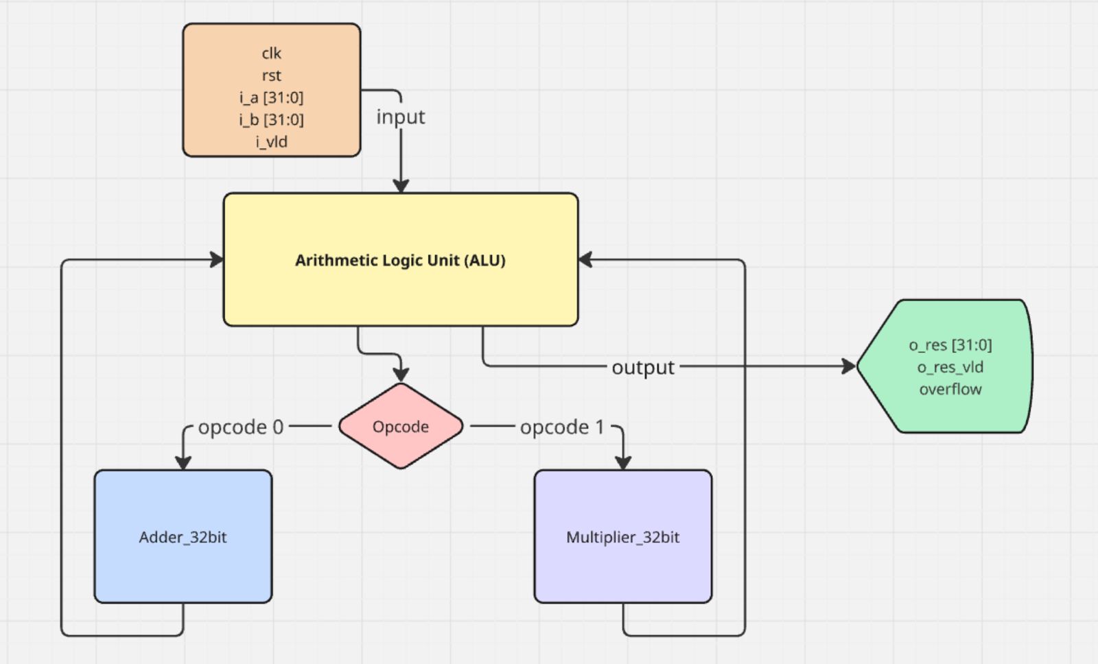
The heart of the system is the Arithmetic Logic Unit (ALU). It controls which operation is performed: addition/subtraction or multiplication, based on a control signal called the opcode. The ALU connects to two functional modules:
- A 32-bit adder (adder_32bit)
- A 32-bit multiplier (multiplier_32bit)
The ALU internally instantiates both of these modules and uses the opcode signal to select which result to propagate to the output.
4.1.2 Operation Control
The opcode is a 1-bit input that decides the operation to be performed:
- opcode = 0: Use the adder to perform addition or subtraction.
- opcode = 1: Use the multiplier to perform multiplication.
4.1.3 Input/Output Structure
The ALU works with the following inputs and outputs:
Inputs:
- clk: Clock signal used to synchronize operations.
- rst: Reset signal to restart the system.
- i_a [31:0]: First input number (32-bit floating-point).
- i_b [31:0]: Second input number (32-bit floating-point).
- i_vld: Input valid signal.
- opcode: Decides which operation to perform (0 for add/subtract, 1 for multiply).
Outputs:
- o_res [31:0]: The result of the operation (32-bit floating-point).
- o_res_vld: Output valid signal (indicates the result is ready).
- overflow: Indicates that the operation resulted in a floating-point overflow condition.
4.2 Block Diagram
5 Implementation
5.1 IEEE Compliant Addition and Subtraction Process
5.1.1 Methodology
5.1.1.1 Operand Decomposition
In IEEE 754 format, each 32-bit floating-point number is broken down into three components: a sign bit (1 bit), an exponent (8 bits) that is biased by 127, and a mantissa (23 bits). For normalized numbers, an implicit leading 1 is assumed before the mantissa, effectively giving it 24 bits of precision during internal computation.
5.1.1.2 Exponent Comparison and Alignment
The exponents of the two operands are first compared. To align the operands for addition or subtraction, the mantissa of the number with the smaller exponent is right-shifted until both exponents match. This ensures both numbers are represented with respect to the same exponent base, allowing a meaningful arithmetic operation.
5.1.1.3 Operation Type Determination
Depending on the operation type (addition or subtraction) and the signs of the operands, the module determines whether to add or subtract the mantissa. If the signs of the operands are the same, their mantissa are added. If the signs differ, the smaller mantissa is subtracted from the larger one to yield the correct result.
5.1.1.4 Mantissa Operation
After alignment, the selected mantissa operation is performed. For operands with the same sign, a direct addition is carried out. For operands with opposite signs, subtraction is performed, with the final sign determined by the operand with the larger absolute value. The result of this step includes a mantissa and a sign.
5.1.1.5 Normalization
Post-operation, the resulting mantissa may need normalization. If the operation produces a carry-out (i.e., a leading 1 beyond the 24th bit), the mantissa is right-shifted and the exponent is incremented. Conversely, if there are leading zeros, the mantissa is left-shifted and the exponent is decremented accordingly until the mantissa is normalized (leading 1 is at the correct position).
5.1.1.6 Rounding
Rounding is applied to ensure the result conforms to IEEE 754 precision requirements. Most commonly, "round to nearest even" is used. Extra bits beyond the 23rd bit—namely the guard, round, and sticky bits—are utilized to decide whether and how to round the result.
5.1.1.7 Result Packing
The final floating-point number is then reconstructed. This involves setting the sign bit based on the outcome of the operation, adjusting and encoding the exponent according to normalization, and trimming the mantissa to its 23-bit representation post-rounding.
5.1.1.8 Special Case Handling
Special cases are also handled to comply with IEEE 754:
- Zero: If the final mantissa is zero, the result is treated as ±0 depending on the sign.
- Infinity: Exponent overflow results in ±Infinity.
- NaN (Not a Number): Arises from undefined operations like Inf − Inf or 0/0.
- Denormalized Numbers: When exponent underflow occurs, resulting in subnormal representations with no implicit leading 1.
5.1.2 Module Description
5.1.2.1 compare_and_shift
Compares exponents of the operands and right-shifts the mantissa of the smaller exponent to align both operands for addition/subtraction.
5.1.2.2 addition_s
Performs mantissa addition or subtraction depending on operand signs.
5.1.2.3 normalization_s
Ensures the result mantissa is normalized by adjusting the exponent and applying leading-zero detection (LZD) or left shift as needed.
5.1.3 Special Case Handling
In compliance with the IEEE 754 standard, the floating-point ALU must correctly handle several special cases to ensure accurate and reliable results across a wide range of operations. These special cases include zero, infinity (±∞), and NaN (Not a Number). Each of these has a specific binary encoding and semantic meaning, which must be detected and handled appropriately during arithmetic operations such as addition, subtraction, and multiplication.
5.1.3.1 Zero
Binary Encoding:
- Exponent: All bits zero (00000000)
- Fraction: All bits zero
- Sign Bit: 0 for +0, 1 for −0
Behavior:
- Treated as exact zero.
- Both +0 and −0 are defined, but generally considered equal in arithmetic.
5.1.3.2 Infinity
Binary Encoding:
- Exponent: All bits one (11111111)
- Fraction: All bits zero
- Sign Bit: 0 for +∞, 1 for −∞
Behavior:
- Represents results of operations that overflow or involve division by zero.
5.1.3.3 NaN (Not a Number)
Binary Encoding:
- Exponent: All bits one (11111111)
- Fraction: Any non-zero value
- Sign Bit: Does not affect meaning
Behavior:
- Represents undefined results.
- Any operation with NaN as input produces NaN.
5.2 IEEE Compliant Multiplication Process
5.2.1 Methodology
5.2.1.1 Operand Decomposition
Each 32-bit IEEE 754 single-precision floating-point input is decomposed into three components:
- Sign bit (1 bit): Indicates the sign of the number.
- Exponent (8 bits): Encoded using a bias of 127.
- Mantissa (23 bits): Represents the fractional part, with an implicit leading 1 added during calculations (for normalized numbers).
This decomposition enables precise control over the arithmetic process and is essential for applying IEEE 754 rules.
5.2.1.2 Sign Calculation
The sign of the result is determined by the XOR of the sign bits of the two input operands. This guarantees that the result is negative only when exactly one of the operands is negative.
5.2.1.3 Exponent Calculation
To compute the correct exponent of the product:
- The biased exponents of the two operands are added.
- The bias value (127) is subtracted from the sum to restore the true exponent.
This maintains IEEE 754 compliance and ensures the exponent properly reflects the magnitude of the result.
5.2.1.4 Mantissa Multiplication
The mantissas, including their implicit leading 1s, are 24-bit values. These are multiplied to produce a 48-bit product, which provides extended precision before normalization and rounding. This intermediate precision ensures that rounding errors are minimized.
5.2.1.5 Normalization
The 48-bit product from the mantissa multiplication is normalized to fit the IEEE 754 format, ensuring the leading 1 appears in the correct position:
- If product[47] = 1, the product is already normalized.
- Otherwise, the product is left-shifted to bring the leading 1 to the MSB, and the exponent is decremented accordingly.
This step ensures the mantissa follows the standard format: 1.xxxxx..., preserving significant digits.
5.2.1.6 Rounding
Only 23 bits of the mantissa can be stored in the final result. IEEE 754 uses Round to Nearest, Even, which requires three additional bits for rounding logic:
- Guard bit: Bit 24 (immediately after the stored mantissa bits)
- Round bit: Bit 25
- Sticky bit: Logical OR of bits 26 and beyond
Rounding Decision:
- Round up if:
- Guard = 1 and (Round = 1 or Sticky = 1), or
- Guard = 1 and the current LSB of mantissa = 1 (to ensure "round to even")
- Otherwise, truncate the mantissa.
- If rounding causes a carry-over (i.e., the mantissa exceeds 24 bits), the mantissa is right-shifted, and the exponent is incremented by 1.
5.2.1.7 Overflow Detection
IEEE 754 reserves exponent values of 255 for special cases like Infinity and NaN. Therefore, the maximum valid exponent for normalized results is 254.
After normalization and rounding:
- If the final exponent exceeds 254, an overflow occurs.
- The overflow condition is flagged, and the output is set to positive or negative infinity, depending on the result's sign.
This prevents misrepresentation and maintains standards compliance.
5.2.1.8 Packing the Result
Finally, the processed components are combined:
- The sign bit (1 bit)
- The adjusted exponent (8 bits)
- The normalized and rounded mantissa (23 bits)
These are packed into the standard 32-bit IEEE 754 format, forming the final product.
5.2.1.9 Special Case Handling
The system handles all IEEE 754 special cases to ensure correct behavior under edge conditions:
- Zero: If either operand is zero, the result is zero.
- Infinity: If one operand is infinity and the other is non-zero, the result is infinity.
- NaN (Not a Number): If any operand is NaN, the result is NaN.
- Overflow/Underflow: Properly detected and flagged during exponent calculation.
5.3 Exception Handling
5.3.1 NaN Propagation
A NaN (Not a Number) result is produced when an operation is undefined or involves an operand that is already NaN. Examples include:
- ∞ − ∞
- 0 × ∞
- Any arithmetic involving an existing NaN
To maintain safe and predictable behavior, a quiet NaN (qNaN) is propagated through subsequent operations. This prevents exceptions from being triggered unnecessarily and ensures that invalid computations do not silently yield valid numeric results.
5.3.2 +Infinity and -Infinity Behavior
Operations involving positive or negative infinity are handled according to IEEE 754 semantics:
- finite + ∞ = ∞
- finite - ∞ = -∞
- ∞ + ∞ = ∞, -∞ + -∞ = -∞
- ∞ - ∞ results in NaN (undefined operation)
The sign of infinity is preserved throughout operations. This behavior is important in scientific and engineering calculations where magnitude and direction (sign) matter.
5.3.3 Zero Result Handling
IEEE 754 distinguishes between +0 and −0, even though they are numerically equal. This distinction is useful in certain edge cases, especially in derivatives or limits. Example behaviors include:
- +0 - +0 = +0
- +0 - -0 = +0
- -0 - +0 = -0
The system ensures that the sign of zero is accurately maintained in the result, complying with the standard's specifications.
5.3.4 Overflow Flag Logic
Overflow occurs when the calculated exponent exceeds the representable range for single precision (greater than 254 for normalized numbers). When overflow is detected:
- The result is set to +∞ or −∞, based on the sign of the operation.
- An overflow flag is raised to indicate this condition.
This helps downstream hardware or software components recognize and respond appropriately to such exceptional results.
5.3.5 Use of Quiet NaN (0x7FC00000)
A standard quiet NaN (qNaN) is encoded using the 32-bit pattern 0x7FC00000. This representation:
- Prevents interruption of computation when a NaN is encountered
- Continues to propagate safely through all arithmetic operations
- Signals that an undefined or invalid value is involved, without raising hardware traps
Using qNaN provides robustness and clarity in floating-point computation pipelines, especially when interfacing with software-level exception handlers.
6. Design Methodology
6.1 RTL Design Using Verilog
The FPALU was implemented using Verilog HDL with a focus on creating clean, well-structured code that adheres to the IEEE 754 single-precision (32-bit) standard. We organized the design into logical modules, each handling specific arithmetic operations, with extensive comments to enhance understanding for educational purposes. The RTL approach allowed us to clearly represent the data flow between registers while maintaining the precision required for floating-point calculations.
6.2 Modular Structure with Clear Input-Output Separation
Our design follows a hierarchical modular architecture that simplifies both development and testing. The top-level module integrates several functional units including dedicated modules for addition/subtraction, multiplication, and division operations. Each module maintains clearly defined input and output interfaces using the standardized floating-point format (1 sign bit, 8 exponent bits, 23 mantissa bits), enabling easy integration and future expansion. This modular approach not only improved code maintainability but also facilitated the parallel development of different arithmetic units.
6.3 Use of Combinational and Sequential Logic
The implementation strategically combines combinational and sequential logic elements to optimize performance and reliability. Combinational logic handles the immediate arithmetic computations, while sequential elements, synchronized to a global clock, manage state preservation and pipelined operations. This hybrid approach ensures both computational efficiency through parallel processing and reliable operation through controlled timing of data movement between stages.
6.4 Synchronous Reset Design
We implemented a synchronous reset mechanism that activates only on clock edges, providing a robust initialization method that prevents metastability issues. This design choice ensures all components reset simultaneously and maintains clean state transitions, which is particularly important for the pipeline registers and control logic. The reset functionality was carefully verified to properly initialize all arithmetic units and status flags.
6.5 Test-Driven Development
Our verification strategy employed separate testbenches for each module, following a test-driven development methodology. Before integrating components, we developed comprehensive test cases for individual modules, ranging from basic operational checks to edge case verification. This approach allowed early detection and resolution of issues at the module level, significantly reducing integration challenges. The testbenches were designed to verify outputs against expected results, with special attention given to exception handling and special number cases.
7 Simulation and Verification
The floating-point unit was verified using the Xilinx Vivado simulation environment, configured to emulate the timing and behavior of the target FPGA hardware. The simulator’s integrated waveform viewer enabled detailed inspection of pipeline activity and timing issues during development. A modular testbench architecture was employed, with individual testbenches designed for each major component of the FPALU. These testbenches generated exhaustive test vectors covering standard arithmetic operations, edge cases, and special IEEE 754 values such as NaN, infinities, and signed zeros. Outputs were automatically compared against expected results, with discrepancies logged and reported for rapid debugging. The test suite encompassed hundreds of cases, including checks for overflow, underflow, and invalid operations, ensuring the design met functional and compliance expectations.
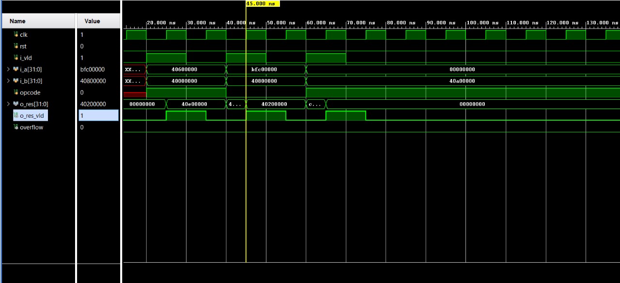
Addition Test Case
 Multiplication Test Case
8 Results
8.1 Functional Correctness of Each Operation
8.1.1 Floating-Point Addition and Subtraction:
- The implementation correctly handles exponent alignment, sign-sensitive operations, and mantissa manipulation. The system adjusts the operand with the smaller exponent to match the larger one, ensuring proper alignment before performing the addition or subtraction.
- The hidden bit (implicit leading 1) is restored for normalized numbers and omitted for subnormals, as required by the IEEE 754 specification.
- The module accurately performs signed addition and subtraction based on the input sign bits. This includes scenarios like adding a negative number to a positive number, which requires internal subtraction and sign adjustment.
8.1.2 Floating-Point Multiplication:
- The multiplication module successfully handles the extraction and separate processing of the sign, exponent, and mantissa fields.
- Mantissas are multiplied using an extended bit-width (to avoid loss of precision), and the exponents are added after bias correction.
- Results are normalized by shifting the product appropriately and adjusting the exponent accordingly.
- Correct sign output is ensured by XORing the operand signs, and bias management ensures valid exponent results.
8.1.3 Overall Arithmetic Behaviour:
- The results of various test cases involving positive, negative, zero, and fractional values were confirmed to match expected outputs using IEEE 754 representations.
- The ALU produced correct outputs for basic and complex arithmetic expressions (e.g., A × B + C) when simulated in sequence.
8.2 Summary of Edge Case Behaviour
8.2.1 Handling of Special Cases:
- Zero Detection and Propagation: When both inputs are zero, the result is zero. The sign bit is handled to preserve the correct result in signed-zero scenarios (e.g., -0 + 0).
- Infinity Handling: If either operand is ±infinity, the result correctly returns ±infinity depending on operation rules. For instance, +∞ + 5.0 = +∞, and -∞ × 3.0 = -∞.
- NaN (Not a Number) Behaviour: If any operand is NaN or if the result of an operation is undefined (e.g., ∞ - ∞), the system returns a canonical quiet NaN (0x7FC00000). This ensures exception-safe propagation of invalid values through computation chains.
8.2.2 Overflow and Underflow Detection:
- The module detects overflow conditions when the computed exponent exceeds the representable range for single precision (greater than 255).
- In the case of underflow, when results fall below the smallest normalized number, the system either produces a denormalized result or zero, as per IEEE 754 behaviour.
8.2.3 Verification through Simulation:
- All modules were verified using Vivado Simulator, with clearly defined testbenches applying a broad spectrum of test vectors.
- Waveform analysis using Vivado provided visibility into signal transitions and state progression, confirming correct sequencing and result generation.
9 Future Work
9.1 Support for Double Precision (64-bit)
The existing design adheres to the IEEE 754 single-precision format. Extending the implementation to support double-precision (64-bit) floating-point arithmetic would significantly improve numerical accuracy and dynamic range. Double precision is particularly essential in scientific computing, aerospace simulations, financial modeling, and medical imaging, where minor inaccuracies can lead to substantial errors.
9.2 Implementation of IEEE-Compliant Rounding Modes
The current design utilizes a simplified rounding strategy, such as truncation or round-toward-zero. However, the IEEE 754 standard defines four rounding modes, which are critical for minimizing bias and improving computational consistency:
- Round to Nearest, ties to Even (default)
- Round Toward Zero
- Round Toward Positive Infinity (+∞)
- Round Toward Negative Infinity (−∞)
Supporting these rounding modes would increase compatibility with standardized floating-point software libraries and improve overall computational accuracy.
9.3 Extension to a Pipelined FPU with FSM-Based Control
To enhance throughput and enable concurrent instruction handling, the current combinational ALU design can be upgraded into a pipelined Floating Point Unit (FPU). This would involve dividing the multiplication operation into multiple pipeline stages such as:
- Operand Fetch
- Alignment
- Execution
- Normalization
- Rounding and Result Writeback
A Finite State Machine (FSM) would be responsible for managing the transitions between pipeline stages, controlling internal timing signals, and coordinating exception handling mechanisms.
Benefits of a pipelined architecture include:
- Increased throughput via parallel processing of floating-point instructions.
- Scalability and modularity for integration into larger processor systems.
- Enhanced compliance with IEEE 754 by isolating and managing corner cases in each pipeline stage.
9.4 Integration with a RISC-V CPU Core
Another logical extension is the integration of the FPU as a coprocessor within a RISC-V processor supporting the F-extension. This would provide a complete system capable of executing floating-point instructions such as fadd.s, fmul.s, and others directly from software.
Such integration would demonstrate real-world applicability and serve as a valuable component in embedded systems, scientific computing devices, and RISC-V-based SoCs.
10 Conclusion
This project presents a modular, IEEE 754-compliant 32-bit floating-point unit capable of performing core arithmetic operations—addition, subtraction, multiplication, and division—along with robust handling of special cases like NaN, infinity, zero, and overflow. Verified through extensive simulation, the design is ready for FPGA implementation and balances precision, performance, and educational clarity. Its modular structure promotes extensibility, testing ease, and portability, making it suitable for both academic and practical applications. Future enhancements, such as double-precision support, pipelining, and optimized rounding modes, can further improve performance and broaden its use in embedded systems, scientific computing, and AI accelerators.
Github Repo:
All the source codes and simulation results can be found here.
Report Information
Team Members
Team Members
Report Details
Created: May 24, 2025, 1:11 a.m.
Approved by: Mayank Singh [Diode]
Approval date: May 25, 2025, 1:43 p.m.
Report Details
Created: May 24, 2025, 1:11 a.m.
Approved by: Mayank Singh [Diode]
Approval date: May 25, 2025, 1:43 p.m.