

IoT Based Smart Door Lock System
Abstract
Abstract
Google meet link- https://meet.google.com/wqu-bhob-srj
Introduction
With technology advancing quickly, Internet of Things (IoT) devices are changing the way we use everyday objects. One such device is the IoT-based smart door lock, which makes it easier and safer to control and monitor doors remotely. Unlike regular locks, these smart locks can be opened using a smartphone. Traditional door locks can be inconvenient and less secure. With a smart door lock, users can monitor doors using a smartphone from anywhere, get instant alerts if someone tries to break in.
The proposed system will use IoT technology to allow users to lock or unlock doors using Wi-Fi capabilities of ESP8266, and get instant alerts if there’s an unauthorized attempt. The project involves implementation of IoT systems and communication protocols, micro-controllers, sensors, modules, Programming in Arduino IDE and mobile apps (e.g. Blynk), Integration of hardware and software components into functional systems.It is a useful solution for modern homes and offices that want better security and convenience.
Methodology
- System Design :
Define the project architecture, including hardware and software components.
Select the required modules for ESP8266 and Arduino. - Software Development:
Program the ESP8266 using the Arduino IDE
Configure the Wi-Fi connection.
Develop code to control the relay with mobile app input.
Send real-time notifications using Blynk. - Hardware Implementation:
Assemble the circuit on a breadboard.
Connect components to the ESP8266.
Relay connections for lock control. - Testing:
Test the system locally to ensure proper functioning of hardware and software.
Component & Analysis
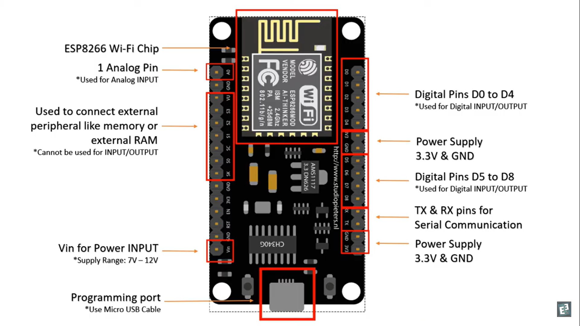
ESP8266 WiFi Module
The ESP8266 is a Wi-Fi microchip with microcontroller capabilities. It is widely used in IoT (Internet of Things) projects because it allows devices to connect to Wi-Fi and be controlled remotely.
Key Features :
1. 17 General-purpose input/output pins (GPIO) to connect sensors, LEDs,
motors, etc. ( GPIO not exposed on NodeMCU kit)
2. Supports UART communication, SPI, I2C, PWM.
3. Wifi operates on 2.4 GHz only.
4. Lower power consumption in sleep mode .
5. Requires development environment as Arduino IDE , NodeMCU Lua firmware
Arduino IDE
An Arduino is an open-source electronics platform designed to make it easy for anyone to create interactive projects. It consists of two main components: a physical microcontroller board (the hardware) and a software environment (the Arduino IDE) used to write and upload code to the board.
Software: You program the Arduino using a simplified version of C/C++ in the Arduino Integrated Development Environment (IDE). The code, called a "sketch," tells the board what to do—like blinking an LED or reading temperature data.
No advanced electronics or programming skills are needed to start. It supports countless projects, from simple blinking lights to complex IoT devices. There’s a huge online community sharing tutorials, code, and ideas
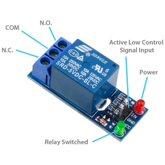
Relay Module 5 volt DC
A relay module is an electronic switch that uses a small electrical signal (from something like a microcontroller or Arduino) to turn a larger electrical load (like a fan, bulb, or motor) on or off.
A 5V relay moduleworks on 5 volts DC, which is commonly used with Arduino, ESP32, ESP8266, and other microcontrollers.
Relay is using vcc as the voltage source for driving relay and activating the optocoupler. Connect Microcontroller's 5v rail to vcc pin and one of the GPIO pins to the IN pin , microcontroller's GND to GND of relay. When GPIO is LOW then syncing current will flow. When it pass through LED inside optocoupler, phototransister will activate. Then main transistor will activate and hence the relay. Switch will flip from NC to NO.
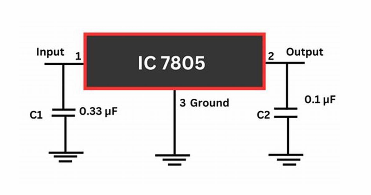
Voltage Regulator 7805
The 7805 takes an input voltage (typically between 7V and 35V) and "regulates" it down to a steady 5V output. It does this by dissipating excess voltage as heat, which is why it’s called a linear regulator. The IC adjusts its internal resistance to maintain the output voltage, even if the input voltage or load current fluctuates (within limits).
Pin Configuration : The 7805 has three pins
1.Input (Pin 1): Where you connect the higher, unregulated voltage (e.g., 9V
from a battery).
2.Ground (Pin 2): The common ground for both input and output.
3.Output (Pin 3): Where you get the regulated 5V.
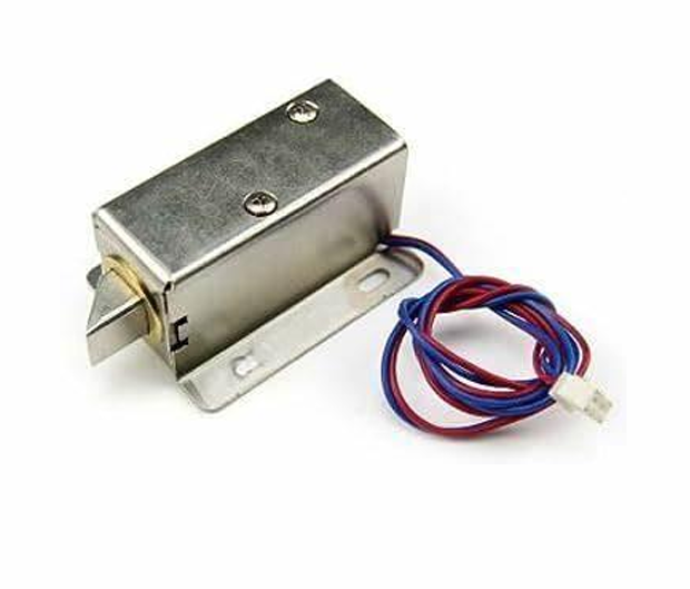
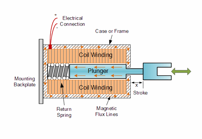
Solenoid Lock
A solenoid lock is an electromagnetic locking devicethat opens or closes when electricity is applied. It is commonly used in smart door locks, cabinets, and security systems.
Inside the solenoid lock, there is a metal pin (or bolt)and a coil of wire. When you apply electric power (usually 12V or 5V DC) to the coil, it creates a magnetic field. This magnetic field pulls the metal pin inside, unlocking the door. When power is turned off, a spring pushes the pin back to its original locked position.
Solenoid lock positive end connected to COM of relay and negative end to battery negative in this project.
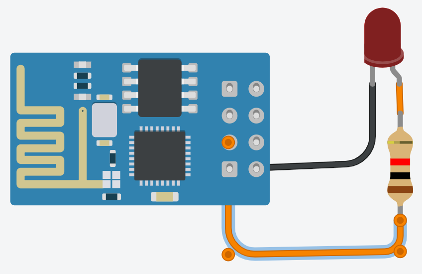
Circuit Schematics & Explanation
A 12V DC adapter or battery is used as the main power source. This is needed because the solenoid lock usually runs on 12V, and other components need 5V.
The 7805 regulator converts the 12V input down to a stable 5V output.
Input (Pin 1): Connect to 12V power supply.
Ground (Pin 2): Connect to system ground.
Output (Pin 3): Provides 5V for the ESP8266 and relay module.
ESP8266, Powered by the 5V output from the 7805. Connect the GND pin of the ESP8266 to the common ground. The ESP8266 controls the relay via a digital pin (e.g., D1 or D2). Also connects to your Wi-Fi and communicates with the Blynk app.
The relay module acts as a switch for the 12V solenoid lock. VCC: Connect to 5V (from 7805). GND: Connect to system ground. IN: Connect to the digital output pin of the ESP8266 (e.g., D1). This controls the relay. Relay has COM (Common), NO (Normally Open), NC (Normally Closed) terminals:
Connect 12V+ from power supply to COM.
Connect NO to + terminal of the solenoid.
Connect – terminal of solenoid to GND.
This way, the solenoid gets power only when the relay is activated.
Here ESP8266 is directly connected to laptop via USB cable, and side one is virtual pin from Blynk App.
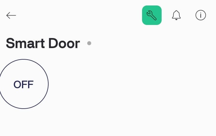
Code and Blynk Notification
We have to create a blynk project , write a code for smart door lock, and then integrate blynk with our project. Blynk is a Platform with iOS and Android apps to control Arduino, Raspberry Pi and the likes over the internet. It's a digital dashboard where you can build a graphic interface for your project by simply dragging and dropping widgets. It connects via Wifi, Ethernet, Bluetooth, Serial USB, 3G. It allows us to interact with pins ( digital and analog ), send and recieve data from hardware with the help of widgets like controllers, displays, notifications, etc.
BlynkSimpleEsp8266.h
This is a commonly used header file in Arduino projects involving \textbf{Blynk} and the \textbf{ESP8266} Wi-Fi module (like NodeMCU or Wemos D1 Mini).
Connects your ESP8266 to the Blynk Cloud or local server
Allows interaction with the Blynk mobile app (e.g., buttons, sensors, notifications)
Enables simple IoT applications without writing complex backend code
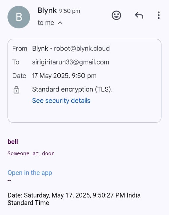
This code controlls the output pin of the ESP8266 which is further connected to relay input (IN), and also send notification to the Blynk app when doorbell button is pressed.
Once the Template is created, we need to copy the Template ID, name, authentication token and paste it in code. When input is triggered, Prints notification ("Someone at door") in the Serial Monitor. Sends a notification to the Blynk app using the created event.
Link for Code and Blynk App integration is given in Demonstration section.
Conclusion
This project successfully demonstrates how IoT technology can be used to create a smart and secure door locking system. By using the ESP8266 microcontroller, Blynk app, and a relay-controlled solenoid lock, users can lock or unlock their doors remotely and receive instant alerts when someone presses the doorbell. The system improves safety, adds convenience, and reduces the need for traditional keys. Through this project, we gained hands-on experience in IoT system design, microcontroller programming, mobile app integration, and hardware-software communication. It is a practical and affordable solution that can be used in homes, offices, or any place that requires smart access control.
Self-Evaluation & Future Projects
By doing this project, I learned a lot about how smart systems work. I got hands-on experience with using the ESP8266 Wi-Fi module, writing code in the Arduino software, and connecting different electronic parts like the relay, voltage regulator, and solenoid lock. I also learned how to use the Blynk app to control devices from my phone. This project helped me improve my skills in both hardware and software, and it made me more confident in building IoT-based systems. Now, I feel ready to take on more advanced projects in the future. This project has opened the door to many exciting possibilities. In the future, I plan to work on: Face Recognition Door Lock System using an ESP32-CAM module , Voice-Controlled Home Automation,
Complete Smart Home System, Battery Backup and SMS Alerts.
Demonstration
https://drive.google.com/drive/folders/1CdM2w3B161W7xkReiqBgZ4Mlk1-e30YM
References
Paperwork on ESP32 - esp32\_datasheet\_en.pdf
Blynk Documentation - https://blynk.io
Wi -Fi Door Lock System Using ESP32 CAM Based on IoT By Trent university grads - (PDF) Wi -Fi Door Lock System Using ESP32 CAM Based on IoT
Nascimento, David Barbosa de Alencar, and Jorge de Almeida "Application of the Internet of Things in the Development of a “Smart” Door 46-IJAERS-MAY-2019-52-Applicationof.pdf
Babiuch, Marek, and Jiri Postulka "Smart Home Monitoring System Using ESP32 Microcontrollers" (PDF) Smart Home Monitoring System Using ESP32 Microcontrollers
Mentors
Tarun.s - +91 74161 85058
Jaya Surya - +91 90320 81105
Rupankar - +91 74395 46839
Mentees
Rahi - +91 90963 63001
Toshith - +91 86606 55042
Devanand - +91 80893 96926
Ramireddy Devendranath Reddy - +91 89190 18066
Bhimpalli Veerendra - +91 80746 56862
Report Information
Report Details
Created: May 25, 2025, 11:41 a.m.
Approved by: Aniruddh Muralidhara Kamath [Diode]
Approval date: May 25, 2025, 12:23 p.m.
Report Details
Created: May 25, 2025, 11:41 a.m.
Approved by: Aniruddh Muralidhara Kamath [Diode]
Approval date: May 25, 2025, 12:23 p.m.