

CFD Simulation of conical modification in double pipe heat exchangers
Abstract
Abstract
1. INTRODUCTION
1.1 Background
Enhancing the thermal performance of double pipe heat exchangers is essential for better heat transfer. Hence, techniques to enhance the heat transfer rate must be employed in the most efficient way. One such method is to modify the tube geometry of double pipe heat exchangers from cylindrical to conical forms. Such a structural change holds the potential to significantly improve thermal performance without increasing the size or weight of the system. Utilization of conical tube instead of cylindrical tube can impress both thermal and frictional characteristics of a heat exchanger. Therefore, the current project investigates the influence of geometry, flow and thermodynamic parameters on heat exchange efficiency. This study also aims to assess the feasibility of conical tube designs for optimized energy transfer.
Computational Fluid Dynamics (CFD) a branch of fluid mechanics that uses numerical methods and algorithms to analyze and solve problems involving fluid flows. CFD helps simulate how gases and liquids interact with surfaces. In CFD, the physical properties of fluids (like velocity, pressure, temperature, and density) are modeled using mathematical equations, and these equations are solved using computer simulations.
1.2 Project Objective
The following are the objectives of the project :
-
To simulate the effect of replacing cylindrical tubes with conical tubes in a double-pipe heat exchanger using computational models.
-
To evaluate the thermal performance of the modified heat exchanger by analyzing parameters such as the Nusselt number and heat transfer rate.
-
To examine the frictional characteristics of the conical tube configuration, including pressure drop and friction factor.
-
To determine optimal geometric and flow configurations for maximizing heat transfer efficiency and minimizing energy losses.
2. METHODOLOGY
2.1 Assumptions and Simplifications
The study assumes steady-state heat transfer conditions, meaning there are no temporal variations in temperature or velocity. Also to neglect the density changes due to temperature variations, the working fluid is treated as incompressible. Assuming incompressibility reduces the complexity of governing equations and eliminates the need for additional terms related to compressibility effects.
To focus on the internal heat transfer behavior, the outer tube is considered adiabatic, meaning no heat loss to the surrounding. The fluid remains in the same phase throughout the heat exchanger. Phase change would introduce additional complexities like latent heat calculations and multiphase flow modeling. The flow is considered fully developed in the heat exchanger, and turbulence is modeled using the k-ε turbulence model.
Frictional and pressure losses are considered uniform across the heat exchanger. In reality, local variations in turbulence and flow separation could affect frictional losses, but these effects are small compared to the overall trends analyzed.
2.2 Geometry
The study involves modifying the cylindrical inner and outer tubes of a double pipe heat exchanger into conical shapes. The conical tubes vary in dimensionless diameter ratios from 1 to 1.73 for certain configurations and from 0.2 to 0.7 for others. The two bodies (conical tubes) under investigation are : cone in cone and cone in cylinder , in comparison to the conventional cylindrical tube.
Table 1 Geometric Modification
|
Label |
Modification Type |
Inside flow |
Annular flow |
|
Mood a |
Cylinder in cylinder |
L —> R |
L —> R |
|
Mood b |
Cone in cone, cocurrent, |
R —> L |
R —> L |
|
Mood c |
Cone in cone, countercurrent |
L —> R |
R —> L |
|
Mood d |
Cone in cone, cocurrent |
L —> R |
L —> R |
|
Mood e |
Cone in cone, countercurrent |
R —> L |
L —> R |
|
Mood f |
Cone in cylinder, cocurrent |
R —> L |
R —> L |
|
Mood g |
Cone in cylinder, countercurrent |
R —> L |
L —> R |
|
Mood h |
Cone in cylinder, cocurrent |
L —> R |
L —> R |
|
Mood i |
Cone in cylinder, countercurrent |
L —> R |
R —> L |
Table 2 Geometry Specification
|
Tube |
b (mm) |
L (mm) |
Di,B (mm) |
Di,S (mm) |
Do,B (mm) |
Do,S (mm) |
|
Outer tube (mood a) |
1 |
500 |
62 |
62 |
62 |
62 |
|
Inner tube (mood b) |
1 |
500 |
30 |
30 |
32 |
32 |
|
Outer tube (mood b-e) |
- |
500 |
102 |
22 |
102 |
22 |
|
Inner tube (mood b-e) |
1 |
500 |
50 |
10 |
52 |
12 |
|
Outer tube (mood f-i) |
- |
500 |
62 |
62 |
62 |
62 |
|
Outer tube (mood f-i) |
1 |
500 |
50 |
10 |
52 |
12 |

Fig.2 The geometric structure of heat exchanger as specified in M. Hashemian et al. / Applied Thermal Engineering 118 (2017)


Fig. 3 Different conical geometries for heat exchanger


Fig. 4 Meshing for different geometries of heat exchanger
2.3 Grid Independence Study
To ensure accurate numerical results, a grid independence study was conducted. The grid independence study is performed on various sizes starting from a coarse mesh to finer meshes. The number of mesh elements ranged from 1880 to 23295, and convergence was achieved at 23295 elements, where deviations in heat transfer coefficient and pressure drop became negligible. Hence, for all the forthcoming simulations the same mesh setting is used.
Table 3 Grid Independence Study
|
Sl. No. |
Element Count |
Heat Transfer Coefficient (HTC) |
Deviation from Previous HTC (%) |
|
1 |
1880 |
795.281 |
— |
|
2 |
5570 |
858.096 |
7.90% |
|
3 |
12098 |
1548.460 |
80.47% |
|
4 |
15020 |
1639.8003 |
5.91% |
|
5 |
19370 |
1685.279 |
2.77% |
|
6 |
23295 |
1685.278 |
0.00% |
2.4 CFD Software and Settings
ANSYS Fluent was used to perform simulations. The governing equations for continuity, momentum, and energy conservation were solved numerically. High-resolution schemes were used for convective terms to improve accuracy.
2.4.1 Turbulence Modeling
Since the Reynolds number indicates fully turbulent flow, the k-ε turbulence model with enhanced wall treatments was selected for modeling boundary layer behavior and turbulence effects.
2.4.2 Boundary Conditions
At the inlet, fluid enters with a predefined mass flow rate and temperature. The fluid flow domain contains an outlet with zero gauge pressure. No-slip boundary condition is applied for all the tube walls. Also, the outer tube is considered adiabatic (no heat loss).
3. RESULTS AND DISCUSSIONS
3.1. Effect of Cold Fluid Temperature:
The Nusselt number decreased with increasing cold fluid temperature across all configurations. This trend is attributed to the reduced thermal driving force, as the temperature gradient between hot and cold fluids diminishes, weakening convective heat transfer.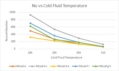
Fig. 6 Variation of Nusselt number with cold fluid temperature
3.2. Effect of Cold Fluid Velocity:
A rise in cold fluid velocity resulted in a marked increase in Nusselt number due to higher Reynolds numbers, which promoted turbulence and improved convective heat transfer. The improvement was most significant in configurations with smaller inner diameters (e.g., Mood b–c), highlighting the importance of tight flow channels for heat enhancement.
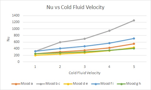
Fig. 7 Variation of Nusselt number with cold fluid velocity

Fig. 8 Eddy viscosity contours for various moods
3.3. Effect of Inlet Velocity:
Higher inlet velocities consistently improved Nusselt number in all test cases. Mood b–c again outperformed the rest, likely due to its narrow channels and high surface-area-to-volume ratio that intensify convective mechanisms. 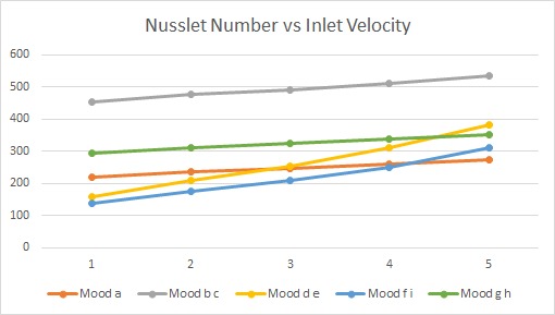
Fig. 9 Variation of Nusselt number with inlet velocity
3.4. Geometry Influence:
Mood b–c exhibited the highest overall heat transfer performance, outperforming the baseline by an average of 85% in Nusselt number. This makes it the optimal configuration among those tested.
Moods f–i, with gradually converging geometries, showed moderate improvements and are better suited for systems where a balance between pressure drop and heat transfer is needed.
Mood a, serving as the reference case, displayed the lowest Nu, emphasizing the need for geometric enhancement to achieve superior thermal performance.
4. CONCLUSION
The project employs CFD as a tool to optimise the design parameters of heat exchangers to obtain the best thermal performance. It has demonstrated that for the specific heat exchanger dimensions, moods b-c serve as the best choice and hence are strongly recommended.
5. REFERENCES
Hashemian, M., et al. “Enhancement of Heat Transfer Rate with Structural Modification of Double Pipe Heat Exchanger by Changing Cylindrical Form of Tubes into Conical Form.” Applied Thermal Engineering, Pergamon, 4 Mar. 2017, www.sciencedirect.com/science/article/pii/S1359431117312267.
Report Information
Team Members
Team Members
Report Details
Created: April 6, 2025, 10:30 p.m.
Approved by: Bhavya Jain [Piston]
Approval date: None
Report Details
Created: April 6, 2025, 10:30 p.m.
Approved by: Bhavya Jain [Piston]
Approval date: None