

Super-Heterodyne Receiver
Abstract
Abstract
 AIM:
AIM:
To design and implement a Superheterodyne Receiver capable of effectively receiving, amplifying, and demodulating high-frequency radio signals by converting them to a fixed intermediate frequency (IF), thereby improving selectivity and sensitivity in radio communication systems.
INTRODUCTION:-
Superheterodyne receiver is a kind of receiver where the incoming signal is multiplied, or “heterodyned” with a local oscillator signal to create a fi xed “intermediate frequency” (IF) signal and then further fi ltered and amplifi ed in order to get a proper audio output. This provides better sensitivity, selectability, as lower frequency IF is easier to work with.
This project will explore the following key components and processes involved in the Superheterodyne receiver:
1. Antenna and RF Front-End: The antenna receives the FM signals from the air, and the RF front-end amplifi es and fi lters the incoming signal.
2. Mixer and Local Oscillator: The mixer combines the incoming RF signal with the local oscillator signal to produce the intermediate frequency.
3. Intermediate Frequency (IF) Stage: The IF signal is fi ltered, amplifi ed, and demodulated to extract the audio information.
4. FM Demodulation: The FM demodulation process extracts the original audio signal from the modulated carrier signal.
5. Audio Amplifi er: The demodulated signal will fi nally get amplifi ed and fed to a speaker for listening to it.
LITERATURE SURVEY:
The superheterodyne receiver, first developed by Edwin Howard Armstrong in 1918, revolutionized radio communication by introducing the concept of frequency mixing to convert a received signal to a lower, fixed intermediate frequency (IF) for easier processing. This architecture quickly became the standard for radio receivers due to its superior selectivity and sensitivity compared to earlier designs such as the Tuned Radio Frequency (TRF) receiver.
In modern implementations, superheterodyne receivers are widely used in applications ranging from AM/FM radios, television tuners, and HAM radios, to military and satellite communication systems. The fundamental principle involves mixing the incoming RF signal with a locally generated oscillator signal to produce an intermediate frequency. This IF is then filtered and amplified before demodulation, allowing for efficient and high-performance signal processing.
Various research studies have explored enhancements in superheterodyne design, including the use of dual-conversion architectures to minimize image frequency interference and digital signal processing (DSP) to replace traditional analog stages. For instance, recent developments have integrated software-defined radio (SDR) concepts into superheterodyne receivers to increase flexibility and reconfigurability.
METHODOLOGY:
RF Stage
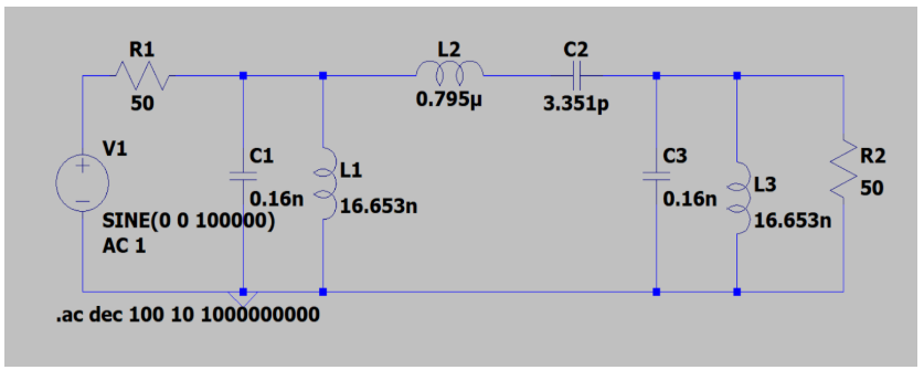
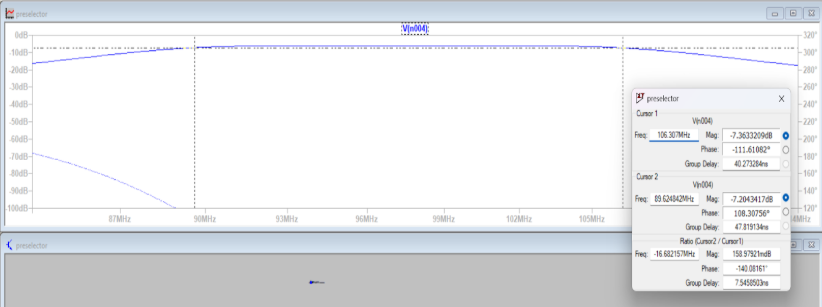
a. Preselect Filter:
This is the first point of contact for the incoming radio frequency (RF) signal. A Butterworth Band Pass Filter is used here due to its flat frequency response in the passband, which helps avoid distortion. The filter is designed to pass signals within the 88–108 MHz FM band, effectively attenuating frequencies outside this range (such as AM signals or high-frequency interference). This stage improves signal-to-noise ratio and prevents strong out-of-band signals from overloading subsequent stages.
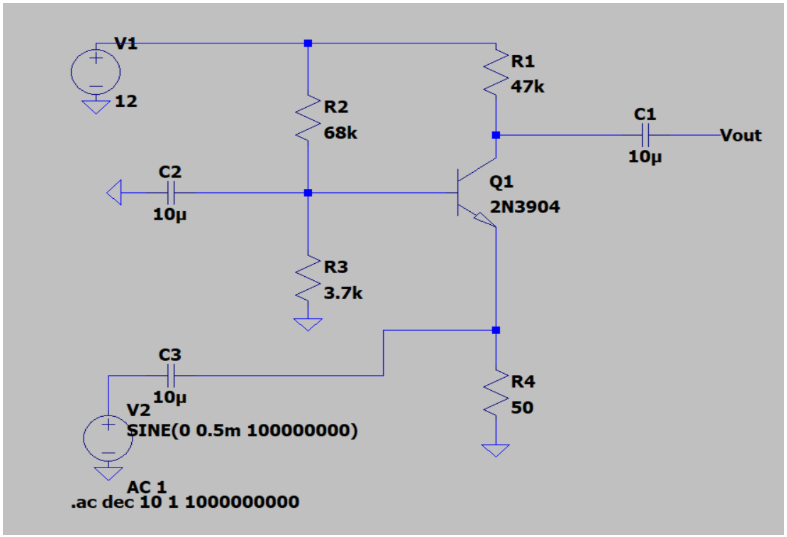
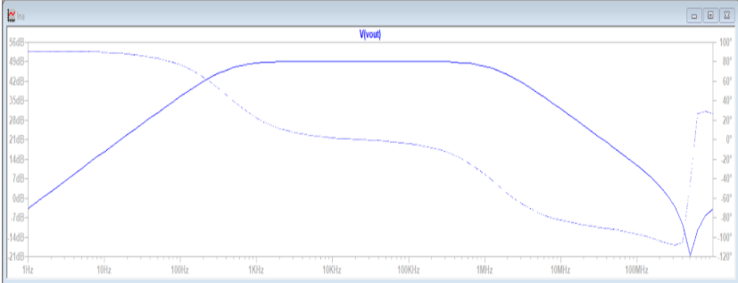
b. Low Noise Amplifier (LNA):
The LNA amplifies the filtered RF signals while contributing minimal additional noise. It uses high-gain, low-noise components such as bipolar junction transistors (BJTs) or MOSFETs to preserve weak signals, especially those from distant or low-power transmitters. Operating within the FM band (88–108 MHz), the LNA ensures that the desired signal is strong enough for effective mixing, without introducing distortion or saturation.
Mixer
The mixer is a nonlinear device that combines the amplified RF signal with the Local Oscillator (LO) signal. This combination results in the generation of two new frequencies: the sum (RF + LO) and the difference (RF − LO). The intermediate frequency (IF), typically 10.7 MHz for FM, is chosen as the difference frequency due to its balance between ease of filtering and good performance characteristics. The mixer may be implemented using diode ring mixers, Gilbert cell ICs, or discrete transistor circuits. Proper shielding is often needed here to reduce unwanted radiation and spurious responses.
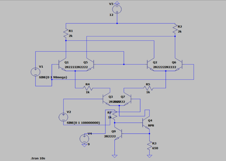
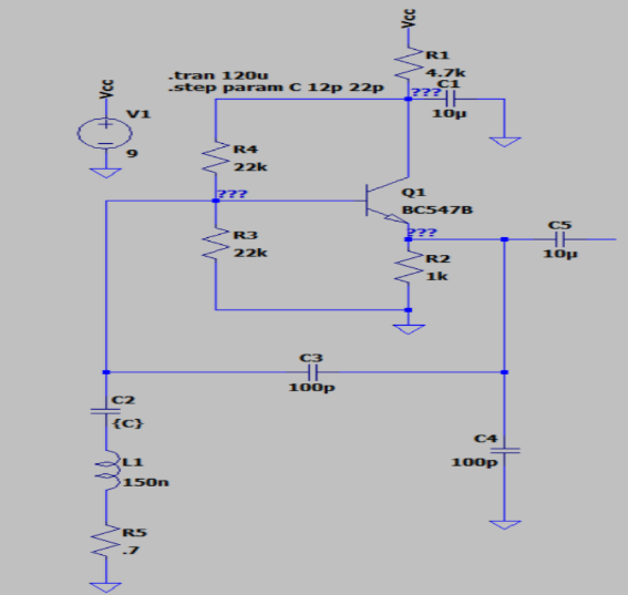
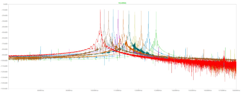
Local Oscillator (LO)
A Colpitts Oscillator, known for its frequency stability and ease of tuning, is used to generate the LO signal. The oscillator frequency is dynamically adjusted depending on the desired station. For FM radio, it typically operates in the range of 98.7–118.7 MHz, which is 10.7 MHz above the incoming RF. This tunable LO ensures that, no matter the RF input, the IF output remains constant, simplifying downstream processing. Component selection (inductors and capacitors) is critical for stability and linear tuning behavior.
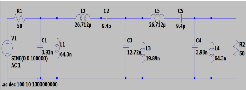
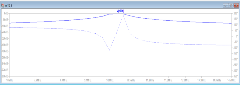
IF Filter
Once the IF signal is obtained from the mixer, it is passed through a band-pass filter centered at 10.7 MHz with a narrow bandwidth (around ±100 kHz for FM). This filter removes the image frequencies and nearby channel signals, allowing only the desired IF signal to pass. Crystal or ceramic filters are often used here due to their high Q-factor and stable response. This stage greatly enhances the selectivity of the receiver, enabling it to isolate a single station even in a crowded frequency spectrum.
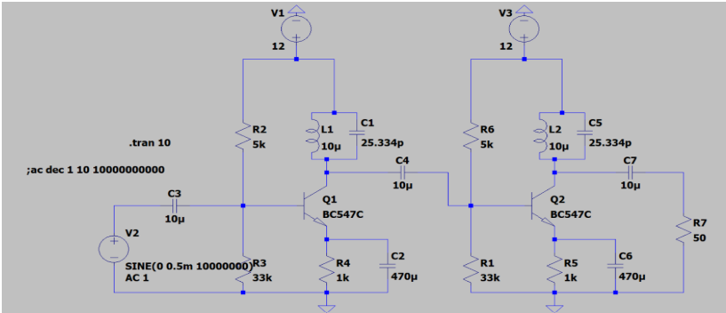
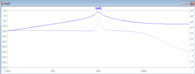
Intermediate Frequency (IF) Amplifier
After filtering, the IF signal is typically weak and needs further amplification. The IF amplifier increases the signal strength while preserving frequency characteristics. It uses high-gain amplifier stages with automatic gain control (AGC) circuitry in more advanced designs, which helps maintain a consistent output level despite varying input strengths. This ensures the demodulator receives a clean, strong signal for accurate demodulation.
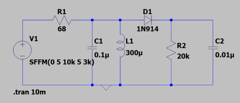
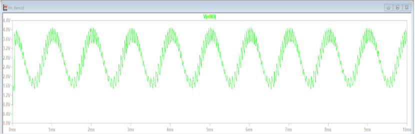
Demodulation
The demodulation stage recovers the original audio or information signal from the modulated IF. For FM signals, a frequency discriminator or quadrature detector is used. These circuits convert the frequency variations of the IF (which carry the audio information) into corresponding voltage variations. The output is then low-pass filtered to remove high-frequency noise, resulting in a clean baseband signal suitable for playback or further processing.
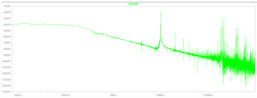
RESULT:
The design and simulation of the Superheterodyne Receiver were successfully carried out using LTspice. Each functional block—including the RF preselect filter, low-noise amplifier, mixer, local oscillator, IF filter, IF amplifier, and FM demodulator—was individually simulated and tested. The RF stage effectively filtered and amplified signals within the FM band (88–108 MHz), and the mixer, when combined with the Colpitts oscillator, reliably downconverted the RF signal to an intermediate frequency of 10.7 MHz. The IF filter provided sharp selectivity, isolating the desired IF signal, while the IF amplifier boosted it without distortion. Finally, the frequency discriminator accurately demodulated the signal, extracting the baseband audio. The successful simulation results validated the theoretical design, demonstrating the feasibility and performance of each stage of the receiver architecture. The LTspice outputs confirmed correct frequency responses, signal amplification, and waveform behavior, indicating that the system can be practically implemented for real-world FM signal reception.
FUTURE WORK:-
● Impedance matching by using LC networks.
● Connecting all the blocks of the receiver.
● Building the hardware using PCB.
ACKNOWLEDGEMENT:
As executive members of IEEE NITK, we are incredibly grateful for the opportunity to learn and work on this project under the prestigious name of the IEEE NITK Student Chapter. We want to extend our heartfelt thanks to IEEE for providing us with the funds to complete this project successfully.
Report Information
Team Members
Team Members
Report Details
Created: April 6, 2025, 11:01 p.m.
Approved by: Aditya Rajesh [Diode]
Approval date: None
Report Details
Created: April 6, 2025, 11:01 p.m.
Approved by: Aditya Rajesh [Diode]
Approval date: None